Fig. 3 — measuring nozzle and plenum pressures, Enclosure selection, Unit – Carrier WEATHERMASTER 36TE User Manual
Page 2: Ptxxm^y thsm
Attention! The text in this document has been recognized automatically. To view the original document, you can use the "Original mode".
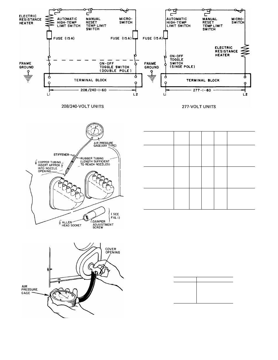
Fig. 2 — 36TE Bypass Weathermaster® Air Terminal Wiring Schematics
Table 1 - Electrical Data and Usage
VOLTAGE/HZ
WATTS
FLA
FUSE
AMPS
WIRE
SIZE
(AWG)
ALLOWABLE
AMP-FT*
1000
4.81
14
332
1500
7 22
12
527
208-1-60
2000
9.63 :
15 0
10
834
2500
12.10
8
1328
3000
14.41
6
p.
2061
1000
4.17
383
1500
6.25
12
609
240-1-60
2000
8.33
15.0
10
962
2500
10.40
8
1533
3000
12.50
6
2378
1000
3.62
14
442
1500
5.42
12
702
277-1-60
2000
7 23
15 0
10
nil
2500
9.03
8
1769
3000
10.85
6
2745
MEASURING NOZZLE PRESSURE
FLA — Full Load Amps
*Copper wire sizes based upon 60 C Use latest National Electric
Code (NEC) for wire lengths (allow 3% voltage drop) and fuse
sizes Follow all local codes required. To obtain maximum wire
length, divide allowable amp—feet by FLA
MEASURING PLENUM PRESSURE
NOTE Unit must not be operated below a 1-in. wg nozzle pres.-
sure and a 1 5-in. wg plenum pressure
Fig. 3 — Measuring Nozzle and Plenum Pressures
3. Total primary air flow to a series of units fed
by a common runout should not exceed 220
cfm.
iMK>RTANTt
Unit
ttoi be operated
With iese
ptxxm^y thsm
sbowjr below:
_ _
ja
IbCC
fif
6;
2&X!
33
JOOO
Enclosure Selection
Standard 36RV enclosures with stamped steel
discharge grilles can be used with the 36TE units.
Plastic grilles must never be used. The steel grille
should be locked in place after installation. On
furred-in units, a discharge grille frame may be
used with the discharge grille.