Carrier WEATHERMASTER 36TE User Manual
Bypass weathermaster® air terminals, Carrier, Ctíons
Attention! The text in this document has been recognized automatically. To view the original document, you can use the "Original mode".
Carrier
ctíons
^ (p 7^h - jr /Q-yc^
Bypass Weathermaster® Air Terminals
INTRODUCTION
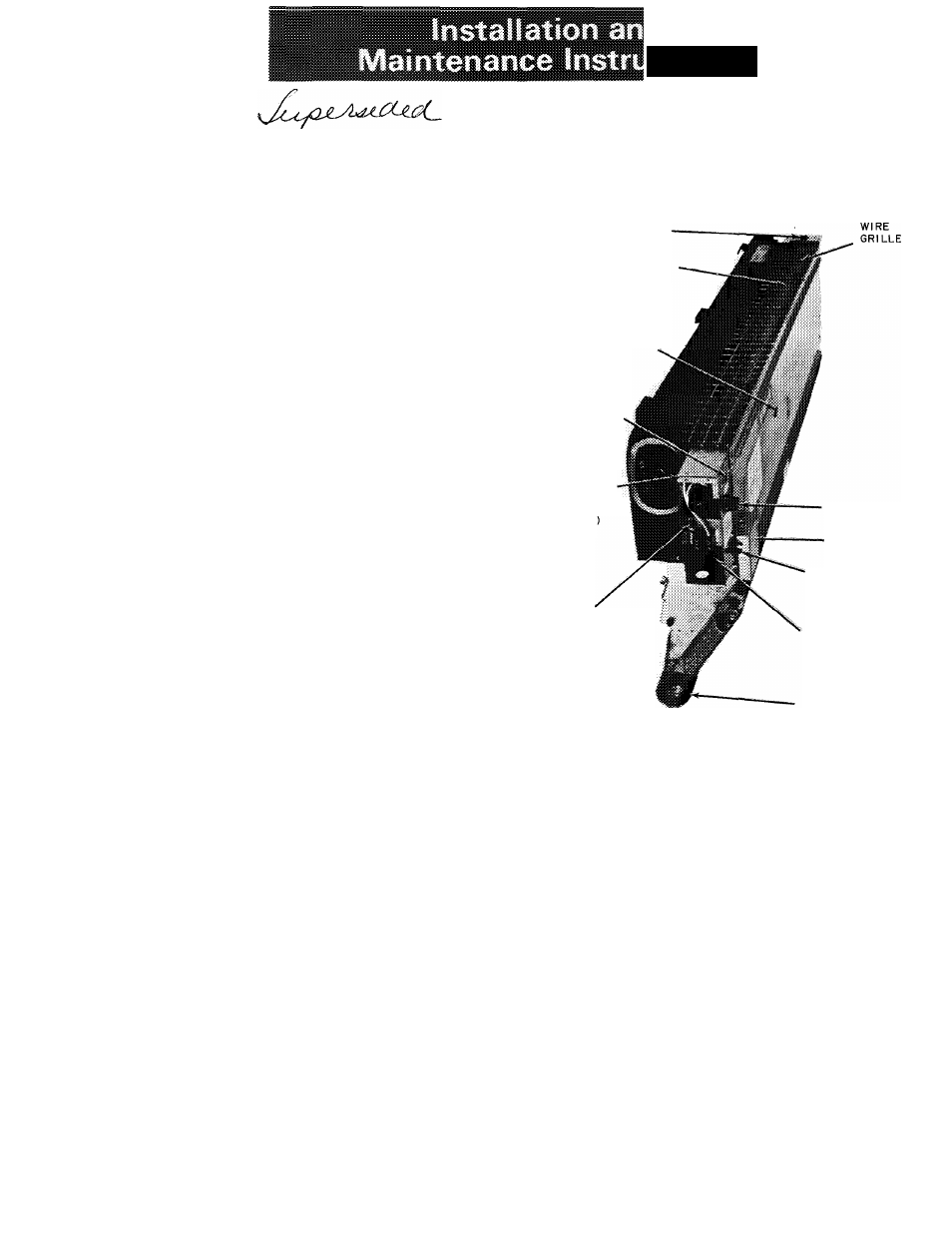
The 36TE unit (see Fig. 1) is a nonchangeover
version of the 36RV Bypass WEATHERMASTER
Air Terminal with an electriciresistance heater. It
consists of an air inlet, sound absorbing plenum,
balancing damper, primary air nozzles, bypass damp
er assembly, secondary coil, and condensate pan.
Controls for this unit are either self-contained
or wall mounted: the thermostat can be mounted
on the right-hand side of the unit or on the wall;
the electrical controls are mounted on the left-
hand side of the unit. Electrical controls include an
On-Off toggle switch, fuse holder, fuse, micro
switch, terminal block, automatic high-temperature
Umit switch, and a manual reset temperature limit
switch.
When the unit thermostat senses a cold room
temperature, it causes the bypass damper to close.
Induced room air is then directed around the
secondary coil. When the damper reaches its full
bypass position, it contacts the microswitch which
activates the heater.
This publication is designed as a supplement to
the 36R Installation Instructions. Since the 36RV
and 36TE units are similar, installation of the
36TE unit is the same as that described for the
36RV unit with the changes noted in this pubhca-
tion. Refer also to the 36R literature for unit and
enclosure dimensional data.
When unpacking unit, should any in-transit
damage be observed, file claim with transportation
agency.
INSTALLATION
Unit Installation
1. Follow procedures outlined for installation of
the 36RV air terminals. Refer to 36R Installa
tion Instructions for details.
2.
Do not remove protective cover from unit
discharge unless discharge grille is being in
stalled. If construction debris is still present in
area, keep discharge covered to prevent debris
from getting into unit heater.
Wiring
1. Observe national and local codes.
2. Check to ensure that unit nameplate voltage
corresponds with the line voltage available at
the job site. Do not exceed the allowable
voltage variation of ± 10 percent.
3. Make line voltage connections to terminal block
in control box on unit. Make ground connec
tion to green screw above terminal block. (See
Fig. 1 and Fig. 2.)
THERMOSTAT
ELECTRIC
RESISTANCE
HEATER
DAMPER
ADJUSTMENT
SCREW (SEE FIG 3)
MANUAL RESET
TEMPERATURE
LIMIT SWITCH
ELECTRICAL
CONTROL BOX
{COVER
REMOVED
GROUND
(CONNECTION)
FUSE
MICROSWITCH
ON-OFF
TOGGLE SWITCH
TERMINAL BLOCK
CONDENSATE PAN
Fig. 1 -36TE Bypass WEATHERMASTER
Air Terminal
4. Refer to Table 1 for electrical data and usage.
NOTE: Whenever the fan in the central station
air handling apparatus is shut down, make sure
that the electric resistance heater located in the
36TE unit discharge is inoperative To ensure
this, the heater circuit should be interlocked
with the apparatus fan.
Unit Balancing
1. Remove construction debris from unit and
make sure that protective plastic has been
removed from thermostat cover.
2. Units are shipped with plenum damper wide
open. Turn damper adjustment screw, which is
located in the front of the unit (see Fig. 1 and
Fig. 3), clockwise to close damper and decrease
nozzle pressure to design value. (Minimum
allowable nozzle pressure is 1.0 in. wg.) Two or
three runs may be necessary to obtain proper
balance. (See Fig. 3.)
NOTE: 36TE unit requires minimum 1.5 in. wg
plenum pressure for control operation; maxi
mum allowable plenum pressure is 5 in. wg.
©Carrier Corporation 1972
Form 36TE-1SI