Recommended timing settings, Figure 5 - single fire wiring diagram – Zipper's Performance 317-105 User Manual
Page 5
Zipper's Performance Products, 6655-A Amberton Dr., Elkridge, MD 21075 Internal Ignition Part No. 317-105
Tel: (410)-579-2828 Fax: (410)-579-2835
www.zippersperformance.com
7/2006
Page 5
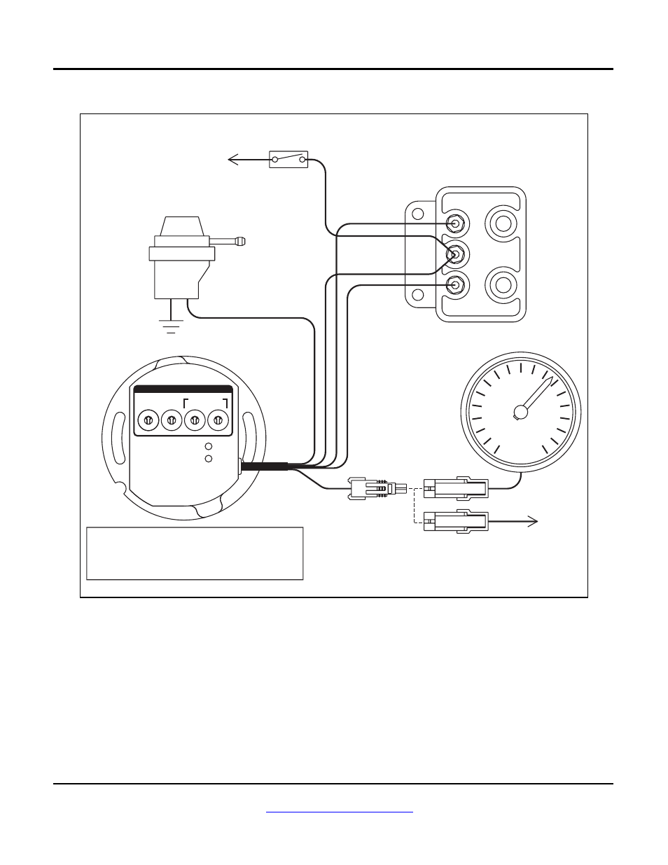
Figure 5 - Single Fire Wiring Diagram
RPM
+
_
_
MODE SETTINGS FOR SINGLE FIRE
2 STREET ADVANCE CURVES, MULTI-SPARK DISABLED
3 STREET ADVANCE CURVES, MULTI-SPARK ENABLED
6 RACE ADVANCE CURVES, MULTI-SPARK DISABLED
7 RACE ADVANCE CURVES, MULTI-SPARK ENABLED
5
0
9
8
6
7
3
1
2
4
6
5
2
4
3
89
0
7
1
6
5
2
4
3
89
0
7
1
6
5
2
4
3
89
0
7
1
STATUS
VOES
MODE
SELECT
X1000
RPM LIMIT
ADVANCE
SLOPE
X100
ADJUST
ENGINE
STOP/RUN
SWITCH
OPTIONAL VOES
(VACUUM SWITCH)
WHITE/BLACK
SINGLE FIRE COIL
WHITE/BLACK
PURPLE/WHITE
TAPE UP WIRE IF
VOES NOT USED
BLUE
TO FRONT
SPARK
PLUG
TO REAR
SPARK
PLUG
OPTIONAL TACH
FEMALE TERMINAL MALE TERMINAL
WEATHER PACK CONNECTORS
BROWN
OPTIONAL CABLE CONNECTED TO
BROWN TACH WIRE DURING PC LINK
TO PC
SERIAL
PORT
TO
+12V
PINK
RECOMMENDED TIMING SETTINGS
Street and race advance curve families are
shown in Figures 6 and 7. Each family has minimum
and maximum curves. The advance slope switch
allows you to run an advance curve in between these
minimum and maximum curves. Advance slope switch
setting zero corresponds to the minimum advance
curve. Switch setting 9 corresponds to the maximum
advance curve. Higher switch settings result in a more
aggressive curve.
Tuning a particular engine setup always requires
some trial and error experimentation, but maximum
power is usually obtained by using the highest advance
setting possible without audible spark knock. Some
recommended starting points are given below:
For stock engines run on normal pump gas (87-
89 octane), use the street advance curves and
advance slope setting 5.
For stock or mildly modified engines run on 92
or higher octane gas, use the street advance curves
and advance slope setting 7.