Locating stove – Vogelzang VG650ELG User Manual
Page 6
Page 6
| VG650ELG MountainEEr™
www
.vogelzang.com
VGZ-025 | 20120424.0
lOCATINg STOvE
1. The stove must be placed on solid concrete,
solid masonry, or when installed on a combus-
tible floor, on a listed UL 1618 Type 2 floor
protector, such as Hy-C or Imperial Model
UL4848BK or equivalent with 1.0 R-factor.
(NOTE: to calculate R-value of alternative
materials see page 20). The base must extend
at least 16˝ beyond the front of the access door,
8˝ to the sides, 8˝ behind and must extend
under and 2 inches beyond either side of the
stove pipe if it is elbowed towards a wall. (See
figures 7 & 9 and consult local building codes
and fire protection ordinances.)
CAUTION: (FIRE hAzARD) CARPETING AND
OThER COMBUSTIBLE MATERIAL MUST NOT
COVER ThE FLOOR PROTECTOR. ThESE
MATERIALS MUST REMAIN OUTSIDE OF
COMBUSTIBLE CLEARANCES, SEE FIG. 7– 9.
2. The stove must have its own flue.
DO NOT
CONNECT ThIS UNIT TO A ChIMNEY
FLUE SERVING OThER APPLIANCES.
3. After observing the clearances to combus-
tible materials (figures 7–9), locate your floor
protector accordingly (figure 7) and care-
fully place the stove in your selected location.
Install connector pipe, elbows, and thimble as
required, utilizing either a recently cleaned and
inspected 6” masonry chimney or a 6” i.d. UL
103 HT listed chimney.
4. Use round 6” dia., minimum 24 MSG (mini-
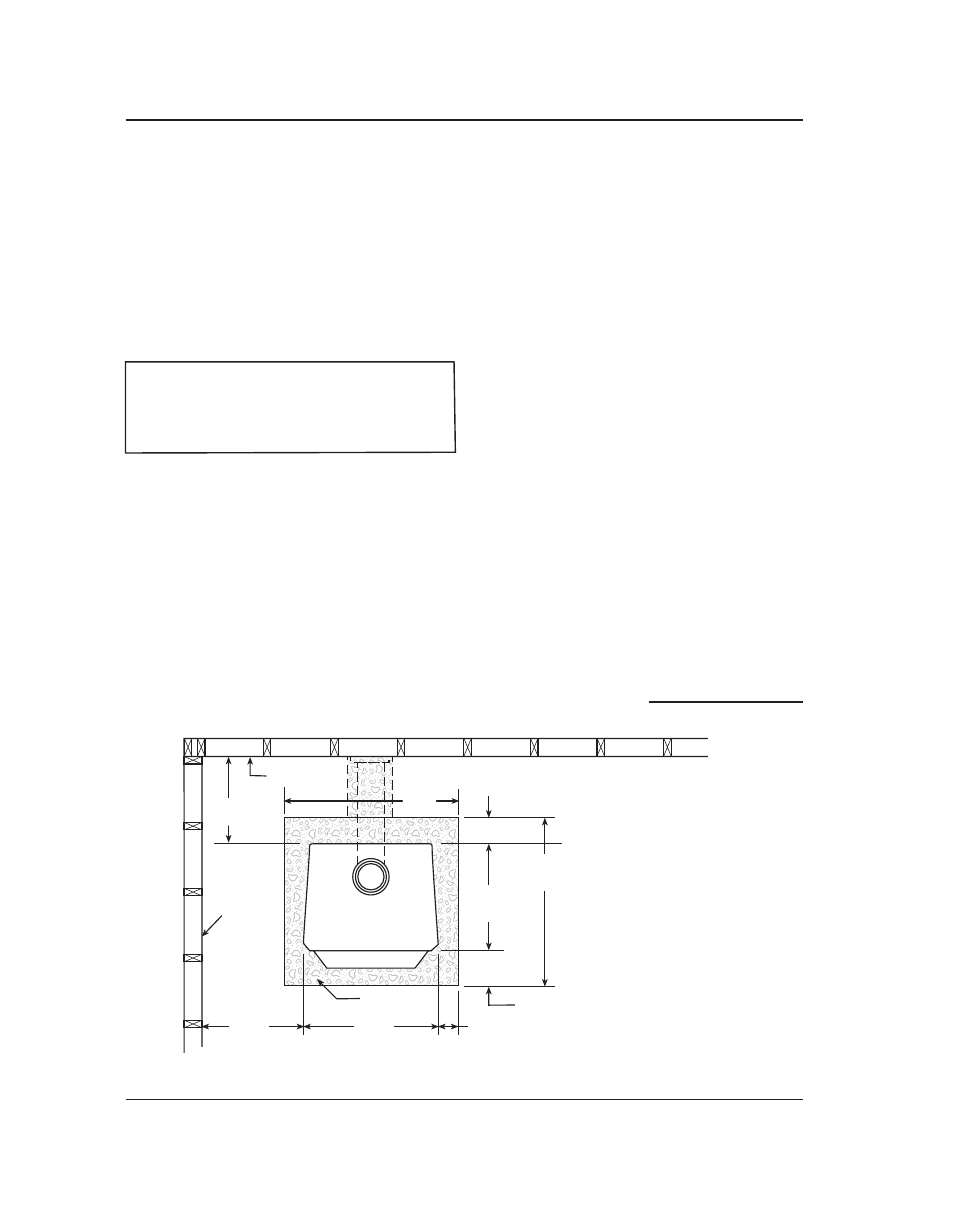
Fig. 7 – TOP VIEw Minimum Clearance Dimensions from Combustible Surfaces
FLOOR
PROTECTOR
DASHED LINES SHOW HORIZONTAL CHIMNEY CONNECTOR
AND ADDITIONAL FLOOR PROTECTOR REQUIRED BENEATH
AND EXTENDING 2” BEYOUND EACH SIDE
COMBUSTIBLE CONSTRUCTION IN ACCORDANCE WITH NFPA 211
BACKWALL
SIDEWALL
8"min.
17"
48"
16"min.
8"min.
28"
25"
min.
26"min
MINIMUM CLEARANCES TOP VIEW
44"
Volgelzang
VG650
Use 48"x 48"
Standard Size
Floor Protector
mum standard gauge) black or 26 MSG blue
steel stove pipe. DO NOT use galvanized stove
pipe. Secure pipe/elbow sections with three
sheet metal screws at each joint to make the
piping rigid. Screws may be no more than a
maximum of 3˝/76mm apart.
DO NOT CON-
NECT ThIS STOVE TO ANY AIR DISTRI-
BUTION OR DUCT SYSTEM.
5. Recheck clearances from the stove, con-
nector stove pipe, and corner clearances
using the illustrations in figures 7–9 and
your local building codes or fire protection
ordinances.
NOTE: A wALL FACED wITh DRYwALL, BRICk
OR STONE MUST BE CONSIDERED A COMBUS-
TIBLE SURFACE.
6.
Do Not iNstall this stove iN a mobile
home, maNufactureD home, teNt or
trailer
– NO EXCEpTIONS!
(HUD Federal
Standard: 24 CFR Ch.xx)
7. The clearances provided are minimum
dimensions determined by US Test Standard UL
1488-1996, tested and applied by Intertek Test-
ing Services, the manufacturer’s testing labora-
tory. Installation of this stove must comply with
the latest edition of NFPA 211 for reduced clear-
ances and/or your local building code rulings.
Use whichever minimum dimensions are
LARGEST.
8. This stove meets U.S. Test Standard:
UL 1482-1996.
continued on next page