Assembly instructions – Vogelzang VG650ELG User Manual
Page 4
Page 4
| VG650ELG MountainEEr™
www
.vogelzang.com
VGZ-025 | 20120424.0
ASSEmblY INSTRUCTIONS
NOTICE: Vogelzang International Corp. grants no warranty, stated or implied, for the installation or maintenance of
your wood stove and assumes no responsibility of any incidental or consequential damages.
tools
TOOLS AND MATERIALS REqUIRED FOR INSTALLATION
• Pencil
• 6 foot Folding Rule or Tape Measure
• Tin Snips
• Drill: Hand or Electric
• 1/8” dia. Drill Bit (for sheet metal screws)
• Screwdrivers (blade and Phillips type)
• 14mm Nut Driver or Ratchet with 14mm Socket
• Safety Glasses
• Gloves
materials
(NOTE: The following items are NOT included with your stove)
Flooring Protection: 48” x 48” as specified (see page 6)
Chimney Connector Pipe: 6” dia. minimum 24 MSG black or 26
MSG blue steel stove pipe or elbow(s) as required.
1/2” Sheet Metal Screws
Chimney: Existing 6” code-approved, lined masonry chimney
or 6” inside dia. Listed UL 103 HT manufactured chimney.
Furnace Cement (manufacturer recommends Rutland Code 78
or equivalent)
CAUTION: STOVE IS hEAVY. MAkE SURE YOU
hAVE ADEqUATE hELP AND USE PROPER
LIFTING TEChNIqUES whENEVER MOVING
STOVE.
1. Uncrate the stove and remove all cardboard
and styrofoam packing materials and protective
poly bag. Remove rear deflector (#2), pedestal
base (#18) and pedestal top (#14) from the car-
ton. (Save cardboard for further assembly.)
2. Remove parts from inside stove. Parts include:
damper (#5), damper collar (#4), blower assem-
bly (#3), ash drawer (#13), pedestal front (#17),
pedestal sides (#15), pedestal drawer support
(#16), and hardware pack (#19) located inside
firebox.
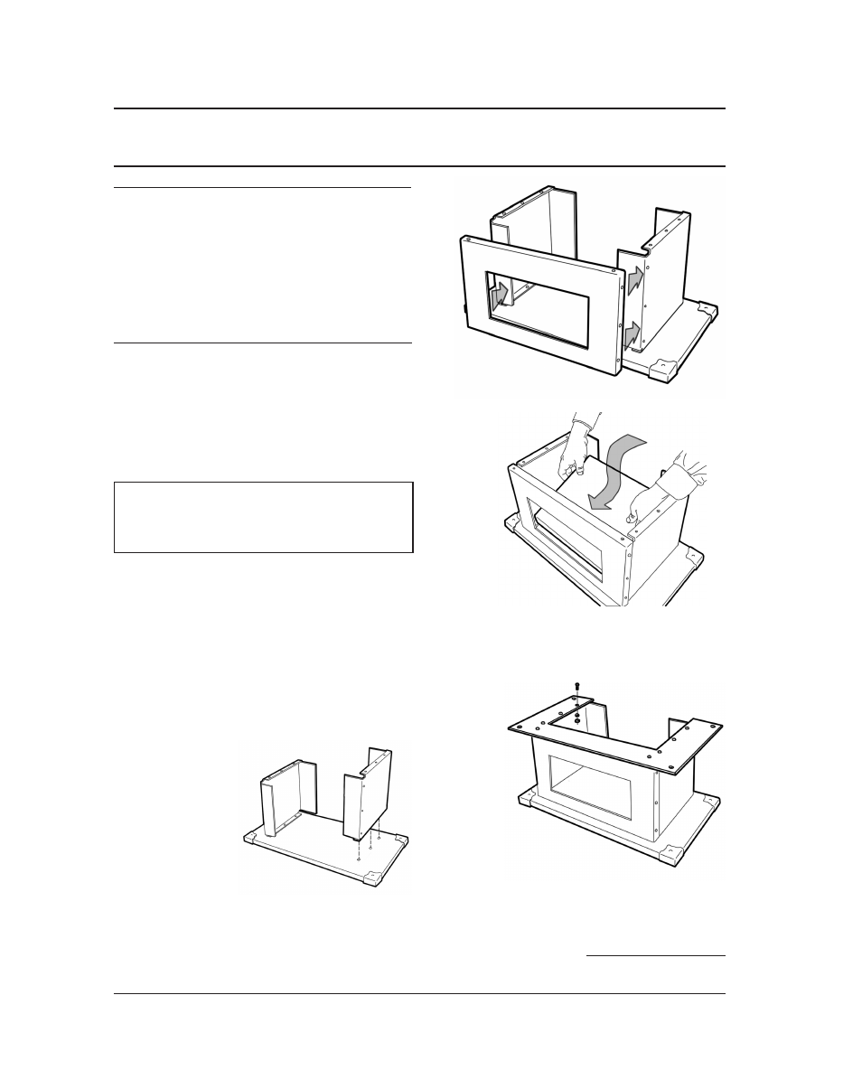
5. Insert the pedestal drawer support (#16) into the
pedestal assembly. Secure with two (2) sheet
metal screws from the back of the assembly.
3. Using machine
s c r ew s , l o c k
washers and hex
nuts, attach the
pedestal sides
(#15) to the ped-
estal base (#18),
figure 1.
4. Attach the front panel (#17) of the pedestal base
assembly to the sides. Notice: the front panel
fits over the sides, figure 2. Attach the front
panel to the side panels with machine screws,
lockwashers and hex nuts (three each side).
Figure 1
Figure 2 Attach Front
Panel to Side Panels.
Figure 3 Insert the
Drawer Support inside the
pedestal base assembly
6. Attach the top plate to the pedestal assembly,
figure 4, with machine screws, lockwashers and
hex nuts.
Figure 4 Attach the
Top Plate to the pedestal
base assembly.
continued on next page