Vogelzang TR004 User Manual
Page 7
TR004M | 11102010.0
TR004 COLONIAL™ |
Page 7
a. Existing fuel-fired equipment show evidence
of back puffing, smoke roll-out, inefficient
operation or excessive smell in the living
area.
b. Opening a window or door alleviates any of the
above problems or symptoms.
c. The building is constructed with a well-sealed
vapor barrier, tight fitting windows or has
powered exhaust fans.
d. Excessive condensation on windows in the
winter.
e. The building has a ventilation system
installed.
f. If, once installed, the solid-fuel appliance does
not draw steadily, burns poorly or inefficiently,
back-drafts or experiences back-puffing when
adding fuel.
vENTING (DRAFT) REqUIREmENTS
The chimney flue is a critical component to the proper
and efficient operation of any heating appliance. Heat-
ing appliances do not create draft, draft is provided by
the chimney. This appliance requires a draft of 0.05 in.
water column (0.1 Pa) at the flue collar.
wARNING: RISk OF FIRE - EXCESSIvE
DRAFT CAN CAUSE OvER FIRING AND POS-
SIBLE STRUCTURE FIRE. DO NOT OPERATE
APPLIANCE wITH FLUE DRAFT EXCEEDING
0.06 in. w.c. (0.1 Pa).
To achieve proper draft, your chimney must meet
three minimum height requirements; minimum height
from top of appliance (15 ft. total height from top of
appliance), minimum height above roof penetration
(3 ft.), and minimum height (2 ft.) above highest point
of roof within a 10 ft. diameter from the chimney. See
Chimney Connections section of this manual.
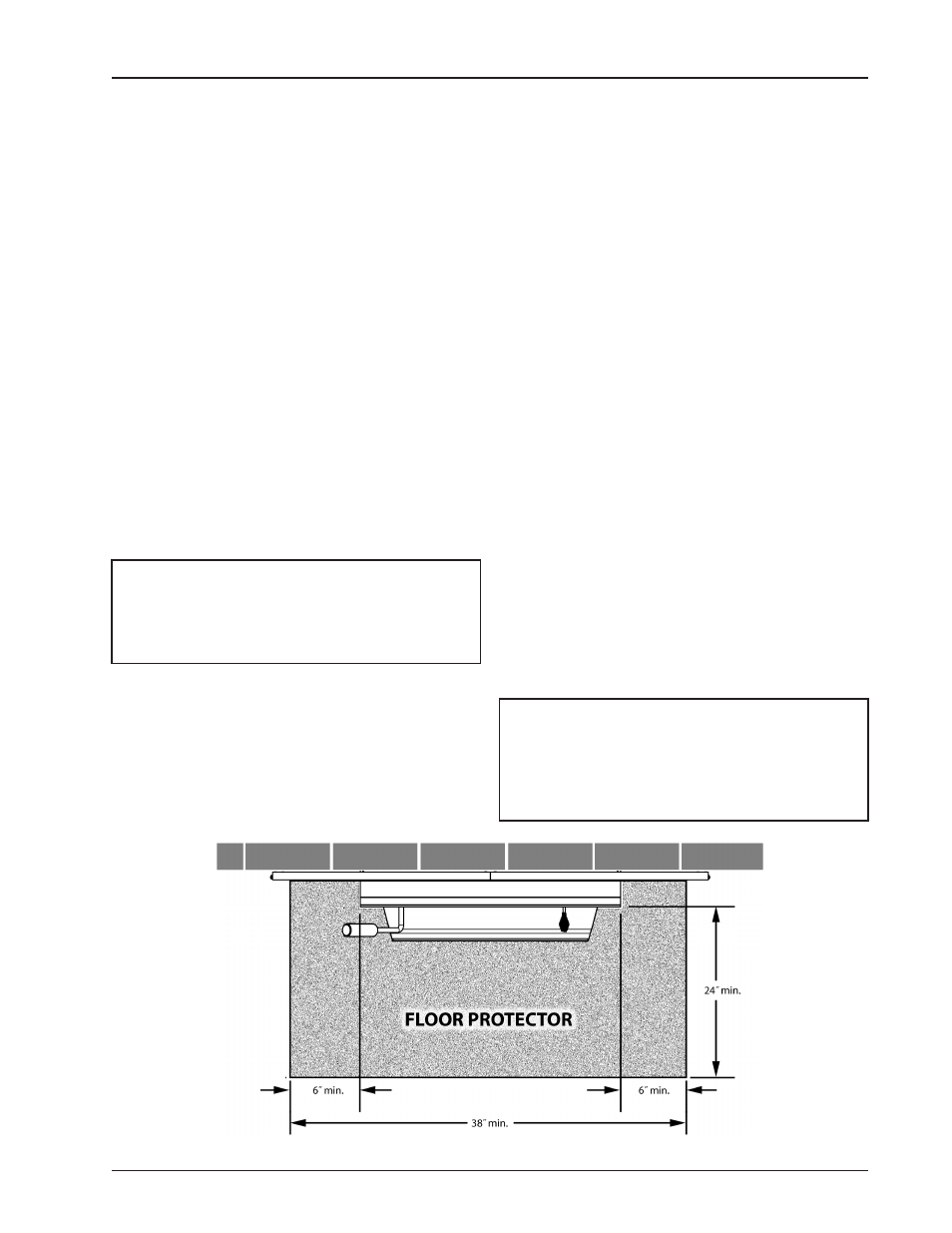
Figure 3 Floor Protector Specifications
The chimney must also meet minimum and maximum
cross sectional requirements. For that reason a con-
tinuous 6˝ stainless steel liner from the flue collar to
the top of the chimney is required. A stainless steel
adapter is recommended for fastening the stainless
steel liner to the flue collar. The male (or crimped) end
of the adapter must be installed
inside the flue collar
to allow condensation or creosote in the liner to drain
back into the firebox. Chimney liners and/or adapters
must be permanently fastened using a minimum of
three (3) screws at each connection.
Chimneys outside of the home or on an exterior wall
are difficult to keep at operating temperatures and
may result in increased creosote buildup, less draft,
back drafting problems and poor appliance perfor-
mance and should be avoided.
FLOOR PROTECTOR
A solid non-combustible floor, concrete or solid ma-
sonry must extend 6˝ to either side of the body of the
insert and 24˝ in front of the face of the insert. This
would require a floor protector 38˝ wide by 24˝ deep.
(See figures 2 & 3)
When combustible flooring falls within these minimum
dimensions, it must be covered with a listed floor
protector such as Hy-C or Imperial Model UL 2840BK
or equivalant with 0.84 R-factor. (Note: to calculate
R-value of alternative materials see
Floor Protector
material Calculations at the back of this manual.)
A grouted ceramic floor tile that meets local building
codes and the minimum 0.84 R-factor requirements is
considered a durable equivalent.
wARNING: RISk OF FIRE. DO NOT ALLOw
COmBUSTIBLE mATERIALS (CARPET, FURNI-
TURE, FUELS) TO BE PLACED ON OR COvER
THE FLOOR PROTECTOR. ALL COmBUSTIBLE
mATERIALS mUST REmAIN OUTSIDE OF THE
mINImUm CLEARANCE DImENSIONS.