Viconics VH20 User Manual
Page 4
Specifications:
General for all sensors
Power supply
Vdc models output
Linear output 0 to 10 Vdc / 0 to 5 Vdc into 2K
resistance min.
24 Vac / Vdc -15%, +10% Vac 50/60 Hz; 1 VA
Power supply
4-20 mA models output
Linear output 4 to 20 mA
12-30 Vdc
Calibration
10 point for 2% models; 3 point for 3% models
Humidity sensing element
10 points calibrated bulk polymer type sensor
Temperature effect
% RH is temperature compensated. Effect is less than 0.1% over the full range (0-100%)
Stability
Less than 1.0 % yearly (typical drift)
Field calibration
-5% / 0% factory / +5% trimmer
Optional temperature sensor
1 % accuracy typical
Maximum wire length
5,000 feet [1,525 m] for 24 GA wire and up
Warranty
18 months from date of purchase or 12 months from date of installation
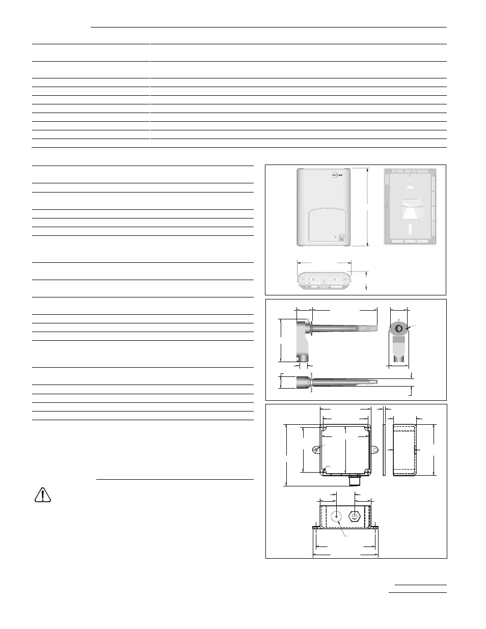
Room sensors (VH20 Wall)
(Fig.5)
Operating conditions:
32
F to 122
F ( 0
C to 50
C )
0% to 95% R.H. non-condensing
Time constant:
Less than 1 minute at 63%
Storage conditions:
-22
F to 122
F ( -30
C to 50
C )
0% to 95% R.H. non-condensing
Dimensions:
(refer to drawing Fig.5)
Appr. shipping weight:
0.4 LBS (0.2 kg )
Enclosure plastic type:
ABS - FRI [WT1337V] UV stabilized
Duct sensor (VH20 Duct)
(Fig.6)
Operating conditions:
-40
F to 122
F ( -40
C to 50
C )
0% to 95% R.H. non-condensing
Time constant:
Less than 10 seconds at 63%
Min. 100 FPM max. 1200 FPM
Storage conditions:
-40
F to 122
F ( -40
C to 50
C )
0% to 95% R.H. non-condensing
Dimensions:
(refer to drawing Fig.6)
Appr. shipping weight:
0.8 LBS [0.4 Kg]
Probe tip plastic type:
Fire retardant grade "HB" ABS
Outside air sensor (VH20 Exterior)
(Fig.7)
Operating and storage
conditions:
-40
F to 122
F ( -40
C to 50
C )
0% to 100% R.H.
Time constant:
Less than 1 minute at 63%
Dimensions:
(refer to drawing Fig.7)
Appr. shipping weight:
1.3 LBS [0.6 Kg]
Enclosure plastic type:
NEMA 4 PVC
Notes:
Humidity sensor is suitable for normal clean air.
Not to be used in corrosive or harmful environment.
Specifications and equipment are subject to change without prior
notice.
Important notice
All VH20 series sensors are for use as operating controls
only and are not safety devices. These instruments have
undergone rigorous tests and verifications prior to shipment to ensure
proper and reliable operation in the field. Whenever a control failure
could lead to personal injury and/or loss of property, it becomes the
responsibility of the user / installer / electrical system designer to
incorporate safety devices ( such as relays, flow switch, high and low
limits, thermal protections, etc…) and/or alarm system to protect the
entire system against such catastrophic failures. Tampering of the
devices or mis application of the device will void warranty.
Viconics Technologies Inc. 9245, Langelier Blvd, St-Leonard, Quebec, Canada H1P 3K9
028-0116
05/04/12 LIT-VH20X-E06.doc
1/2" [13 mm] FPT
Ø 0.75" [19 mm]
7.00" [178 mm]
1.30" [33 mm]
4.40" [112 mm]
1.75" [44 mm]
2.10" [53 mm]
Ø 5/32" [4 mm]
c/c 1.75" [44mm]
Fig.6
4.00"
[102 mm]
4.88" [124 mm]
3.45"
[88 mm]
3.67" [93 mm]
* Threaded
brass insert
Ш 8-32*
Ш 0.25"
[6 mm]
Ø 7/8"
[22 mm]
1.63"
[42 mm]
c/c 4.68" [119 mm]
5.25" [133 mm]
1.19" [30 mm]
1.19" [30 mm]
2.00"
[51 mm]
4.00" [102 mm]
3.45" [88 mm]
0.25" [6 mm]
2.125"
[54 mm]
Fig.7
Fig.5
3.38" [86 mm]
1.13" [29 mm]
4.94" [125 mm]