Viconics VH20 User Manual
Page 2
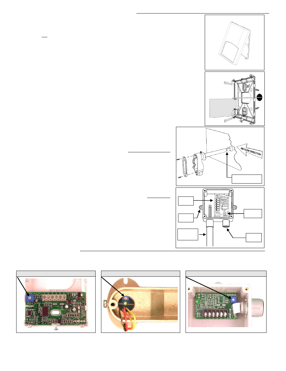
Fig. 2
Installation of room sensors (VH20 Wall) (Fig. 1 & 2)
Remove security screw on the bottom of sensor cover.
Open up by pulling on the bottom side of sensor. (Fig.1)
Location:
1- Should not be installed on an outside wall.
2- Must be installed away from any heat source.
3- Should not be installed near an air discharge grill.
4- Should not be affected by direct sun radiation.
5- Nothing must restrain vertical air circulation to the sensor.
Installation:
1. Remove security screw on the bottom of thermostat cover.
2. Open up by pulling on the bottom side of thermostat.
3.
Pull out cables 6” out of the wall.
4. Wall surface must be flat and clean.
5. Insert cable in the central hole of the base.
6. Flip printed circuit board to access mounting hole
7. Align the base and mark the location of the two mounting holes on the wall.
8. Install proper side of base up.
9. Install anchors in the wall.
10. Insert screws in mounting holes on each side of the base. DO NOT OVERTIGHTEN
11. Strip each wire 1/4 inch.
12. Insert each wire according to wiring diagram.
13. Gently push back into hole excess wring back into the wall.
14. Press back printed circuit board into place
15. Install the cover, top side first
16. Install security screw.
Installation of duct sensors (VH20 Duct)
– (Fig.3)
1.
Drill 1” [25mm] hole mid height on the side of the duct to insert the probe.
2. Direct the probe so that the flat side of probe tip is facing the airflow.
3. Mark the position of the two holes to be drilled for mounting the sensor on the
duct. Fasten the sensor to the duct with the two self-taping screws ( not-
included ). Do not overtighten!
4. Junction box must be directed downwards or sideways.
5. For best results, locate sensor as far as you can from heating/cooling source.
Installation of outside air sensor (VH20 Outdoor)
– (Fig.4)
1. Install sensor using mounting holes on each side.
2. Install on a vertical surface, respect mounting orientation
3. Remove the four screws and remove the cover.
4. Strip each wire 1/4 inch.
5. Insert each wire according to wiring diagram.
6. Install the cover with supplied screws.
7. In snowy area allow sufficient height for snow accumulation.
Maintenance of transmitter
Calibration: The transmitter is factory calibrated. However, it can be field recalibrated by using the ( -5%, 0%, 5% ) potentiometer
inside the transmitter to adjust the zero. The transmitter is already factory calibrated to the center of the potentiometer. To
recalibrate the transmitter to the factory preset, turn the potentiometer to the 0% adjustment. (see pictures below)
VH20 Wall mounted
VH20 Duct mounted
VH20 Outdoor
Cleaning: The VH20 duct sensor probe needs inspection annually to be cleaned of any excess dirt on the sensing element tip.
The whole filter tip can be ordered and replaced if it cannot be cleaned properly. Part number: VH20DuctTip.
Fig. 1
Fig.3
Probe tip, flat side
facing airflow
Fig.4
Calibration
+/- 5% RH
Sensing
probe
PCV conduit
Adapter by
others
Wiring
terminal
Mounting
hole