Viconics R842 User Manual
Page 5
5
1
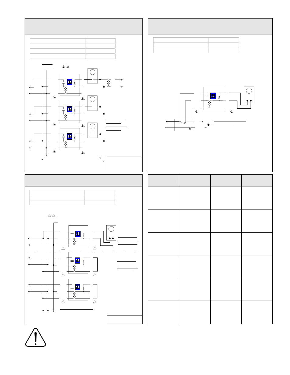
High voltage blue wire is always connected. R842 units are powered devices.
2
Provide overload protection and disconnect as required.
3
Do not use 24 Vac terminal #1 as power supply to an electronic thermostat. Use a separate transformer.
4
L1, L2 & L3 can be mixed / matched.
5
Operates only if all relays control the same phase of a 3 phase system or on a single phase branch.
Multiple two wire low voltage thermostats using the
same separate 24 Vac transformer to control
multiple R842 baseboard relays
Viconics T186 sensor to control
one R842 baseboard relay
Viconics T186 sensor for
master / slave arrangement of R842 baseboard relays
Model
Volt
Resistive
Rating (A)
Inductive
Rating (HP)
R842-120 120
22
½ HP
8 Amp
R842-208 208
22
1 HP
8.8 Amp
R842-240 240
22
1 HP
8 Amp
R842-277
277 19 N/A
R842-347
347 18 N/A
Electrical Specifications:
R842-600
600 10 N/A
Baseboard(s) / load(s)
One
Relay(s)
One
T186 thermostat
One
Baseboard(s) / load(s)
Multiple
Relay(s)
Multiple
Thermostat(s)
Multiple
Transformer
External
Adjust thermostat
anticipator to 0.1 A
or less.
Load side
RED
BLACK
BLUE
Internal circuit
RED
BLACK
BLUE
Internal circuit
RED
BLACK
BLUE
Internal circuit
L1
L2 / N
Load side
Load side
2 wire low
voltage thermostats
L1
L2 / N
Separate remote
24 Vac
transformer
Set both switch
on all relays
to factory default
ON position
1
2
ON
1
2
ON
1
2
ON
3
2
1
3
2
1
3
2
1
Junction box
Load side
RED
BLUE
Internal circuit
L1
L2 / N
T186 sensor
2 wire non polarized
Set both switch on relay
to OFF position
1
2
ON
3
2
1
BLACK
Baseboard(s) / load(s)
Multiple
Relay(s)
Multiple
T186 Thermostat
One
Note: Slave units life cycle is
100,000 cycles
RED
BLACK
BLUE
Internal circuit
1
2
3
1
RED
BLACK
BLUE
Internal circuit
1
2
3
RED
BLACK
BLUE
Internal circuit
1
2
3
1
1
L1
L2 / N
2
Load side
3
3
3
5
Install a jumper
across terminals
1 and 3 on all
slave relays
1
2
ON
Set both switch
on master relay
to OFF position
1
2
ON
1
2
ON
Master
Slave(s)
Load side
Load side
Maximum of 10 slave units
Set both switch
on slave relays
to factory default
ON position
T186 sensor
2 wire non polarized