Installation – Viconics R842 User Manual
Page 3
3
Electric baseboard strip
Secure inside cabinet
using mounting screws
Installation
Important: All wiring must conform to local and
national electrical code regulations. Please read
these instructions carefully before the installation.
Failure to follow the instructions could damage the
product or cause a hazardous condition. Installation
must only be performed by a qualified service
technician. Disconnect power supply before installing
in order to prevent electrical shock. There are two
basic methods to install the R842 baseboard relay.
A. Installation Inside Electric Baseboard
B. Junction Box Installation
Use the supplied lock nut to secure the relay to the
electrical junction box. It is possible to mount the relay
completely inside the junction box or outside, as
desired. In the case of the former, make sure that the
front of the R842 relay is facing the cover of the junction
box. For mounting outside of the junction box, make
sure that the front of the relay is visible. In both cases,
this will permit the installer to view the red LED in order
to confirm operation.
Fig.4 - R842 relay installation
Fig.5 - R842 relay, installation in an electrical junction box
1. Use the plastic mounting tabs to secure the unit
to the inside of the electrical enclosure.
2. Secure to the cabinet with screws.
3. Cut one or both plastic mounting tabs if space is
needed inside the enclosure.
4. If a high voltage separation barrier is needed,
please contact the baseboard manufacturer.
5. Do not exceed the maximum rated temperature
of the R842 unit. (65
°C/149°F)
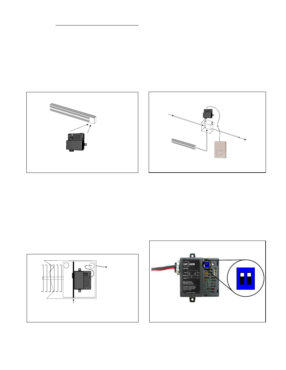
Dip Switch Settings
Whenever using one R842 relay, please set the dip
switches as follows, depending on the input signal:
1. Two wire low voltage electromechanical thermostat:
set both switches to "ON"
2. Viconics' T186 set both switches to "OFF"
For all applications involving multiple R842 relays,
please refer to the diagrams on pages 4, 5, and 6
Fig.6 - R842 relay, installation inside baseboard cabinet
Fig.7 - R842 relay, location of dip switches
If a high voltage separation barrier is needed,
please contact baseboard manufacturer
24 Vac Low voltage
control wires to
thermostat
Refer to wiring diagrams for dip switch setting
per application.
1
2
ON
1
2
ON
High voltage
wires
24 Vac Low voltage
control wires
Standard 4 "x 4" junction box
installed in the ceiling
Electric baseboard strip
To other high voltage
juction boxes
From other high voltage
junction boxes
T186 sensor