Typical applications & wiring – Viconics R842 User Manual
Page 4
4
Typical applications & wiring
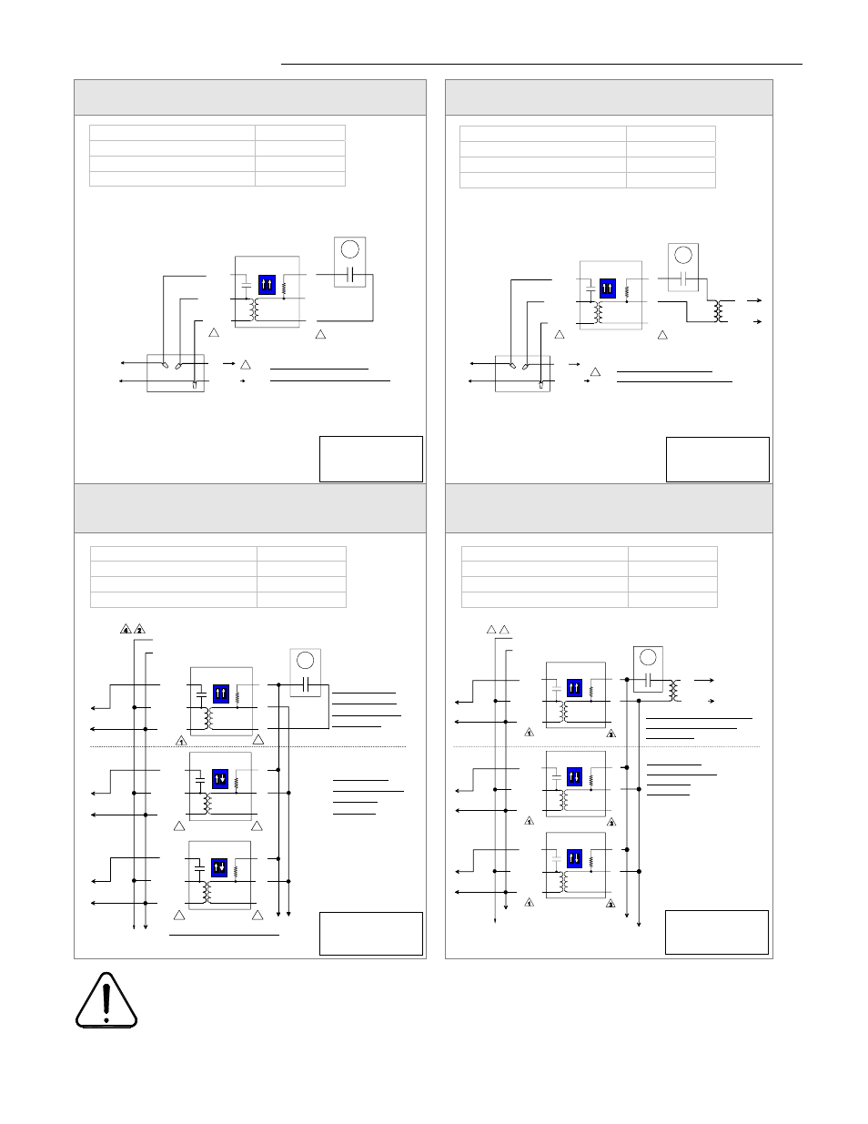
Two wire low voltage thermostat using R842 baseboard
relay internal transformer
Two wire low voltage thermostat using a separate
24 Vac transformer
Two wire low voltage thermostat using R842 baseboard
relay internal transformer for multiple relay
arrangement
Two wire low voltage thermostat using a separate
24 Vac transformer for multiple relay arrangement
1
High voltage blue wire is always connected. R842 units are powered devices.
2
Provide overload protection and disconnect as required.
3
Do not use 24 Vac terminal #1 as power supply to an electronic thermostat. Use a separate transformer.
4
L1, L2 & L3 can be mixed / matched.
5
Operates only if all relays control the same phase of a 3 phase system or on a single phase branch.
Baseboard(s) / load(s)
One
Relay(s)
One
Thermostat(s)
One
Transformer
Internal
Baseboard(s) / load(s)
One
Relay(s)
One
Thermostat(s)
One
Transformer
External
Baseboard(s) / load(s)
Multiple
Relay(s)
Multiple
Thermostat(s)
One
Transformer
Internal
Baseboard(s) / load(s)
Multiple
Relay(s)
Multiple
Thermostat(s)
One
Transformer
External
Adjust thermostat
anticipator to 0.1 A
or less.
Adjust thermostat
anticipator to 0.1 A
or less.
Adjust thermostat
anticipator to 0.1 A
or less.
Adjust thermostat
anticipator to 0.1 A
or less.
Junction box
Load side
RED
BLACK
BLUE
Internal circuit
L1
L2 / N
1
2
2 wire low voltage
thermostat
3
1
2
ON
Set both switch on relay
to factory default ON position
3
2
1
Junction box
Load side
RED
BLACK
BLUE
Internal circuit
L1
L2 / N
1
2
2 wire low voltage
thermostat
L1
L2 / N
Separate remote
24 Vac transformer
3
1
2
ON
Set both switch on relay
to factory default ON position
3
2
1
Load side
RED
BLACK
BLUE
Internal circuit
RED
BLACK
BLUE
Internal circuit
RED
BLACK
BLUE
Internal circuit
L1
L2 / N
2
Load side
Load side
2 wire low
voltage thermostat
Separate remote
24 Vac transformer
4
1
2
ON
1
2
ON
1
2
ON
3
2
1
3
2
1
3
2
1
L1
L2 / N
Master
Slave(s)
Set both switch on master
relay to factory default
ON position
Set switch on
all slave relays to
S1 = ON &
S2 = OFF.
1
RED
BLACK
BLUE
Internal circuit
2
2 wire low
voltage thermostat
1
2
ON
Set both switch
on master relay
to factory default
ON position
Set switch on
all slave relays to
S1 = ON &
S2 = OFF.
1
RED
BLACK
BLUE
Internal circuit
2
3
1
2
ON
1
RED
BLACK
BLUE
Internal circuit
2
3
1
2
ON
Master
Slave(s)
Maximum of 10 slave units
3
Load side
L1
L2 / N
Load side
Load side
1
1
3
3
3