Viconics VRP5000 (Classic ZigBee) Installation Manual User Manual
Page 2
0028-0265-04
2
www.viconics.com / [email protected]
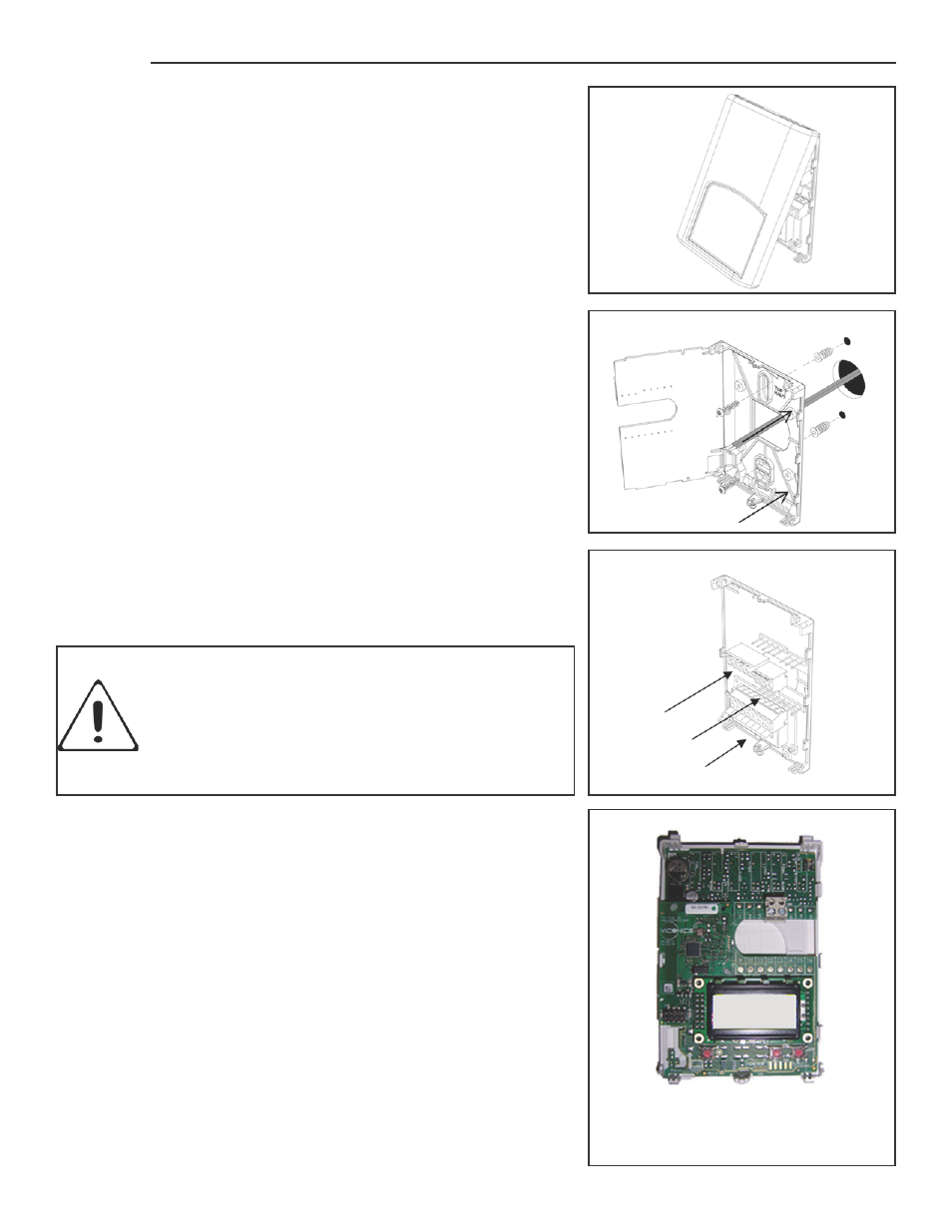
Installation
• Remove security screw on the bottom of repeater cover.
• Open cover by pulling on the bottom edge of repeater.
• Remove assembly and then remove wiring terminals from sticker.
(Fig. 3)
• Please note the FCC ID and IC label installed in the cover upon
removal of cover of the wireless products.
A) Installation ( wall or within suspended ceiling ):
1- Swing open the repeater PCB to the left by pressing the PCB
locking tabs.
(Fig. 4)
2- Pull cables 6” out of the wall.
3- Mounting surface must be flat and clean.
4- Insert cables in the central hole of the base.
5- Align the base and mark the location of the two mounting holes on
the wall. Install with proper side of base facing up.
6- Install anchors if required.
7- Insert screws in mounting holes on each side of the base.
(Fig. 4)
8- Gently swing back the circuit board on the base and push on it
until the tabs lock.
9- Strip each wire 1/4 inches from end.
10- Insert each wire according to wiring diagram.
11- Gently push excess wiring back into hole
(Fig. 5).
12- Re-Install wiring terminals in correct location.
(Fig. 5).
13- Reinstall the cover (top side first) and gently push extra wire length
into the hole in the wall.
14- Install security screw.
Fig. 3
Location of PCB retaining tabs
Fig. 4
Re-install terminal blocks
Fig. 5
• Electronic controls are static sensitive devices.
Discharge yourself properly before manipulating and
installing the controller.
• A short circuit or wrong wiring may permanently dam-
age the controller or the equipment.
Repeater assembly
(VRP5000W)