Basic initial design and deployment considerations – Viconics VST5000 (Classic ZigBee) User Guide User Manual
Page 3
3
VST5000W5000W
Wireless Survey Tools User Guide
IEEE 802.15.4 along with ZigBee Networks and
Application Support Layer provide:
• Low cost installation deployment
• Ease of implementation
• Reliable data transfer
• Short range operation
• Very low power consumption
For a successful ZigBee deployment, it is important to
understand that the ZigBee wireless network is
influenced by the same environmental factors that
affect other wireless systems:
• Interference from radio emitters
• Various electronic devices
• Interference caused by solid objects that may
slow or stop communication between devices
Even with potential sources of signal interference,
the presence of these factors should not result in
noticeable network performance degradation.
Environmental issues will occur with any wireless
network installation.
Basic Initial Design And Deployment
Considerations
Proper design considerations need to be addressed
prior to any installation of a JACE with a Viconics wireless
communication card and related wireless controllers.
• Viconics recommends using a per floor horizontal
architecture vs. a vertical one. Transmitting from
one floor to the other may be possible in certain
applications (such as going through stair ways),
but the design and optimization of the controller
antenna is designed for optimal horizontal distance
penetration and not a vertical one. As such, be
prepared to use AT LEAST ONE coordinator (VWG /
Jace-Driver) per floor.
• Please note that radio transmissions CANNOT travel
through steel. If floors are constructed with steel
joists or other steel materials it is highly unlikely
that the wireless controller transmissions will be
successful between floors.
Clear line of sight deployment
• To avoid network interference with 802.11 Wi-
Fi devices in the 2.4GHz spectrum, Viconics
recommends the use of 802.15.4 channels 15, 25 and
26 ONLY. 802.11 Wi-Fi transmissions overlap and may
interfere with other channel selections allowed by
802.15.4 (Channels 11 to 24 ).
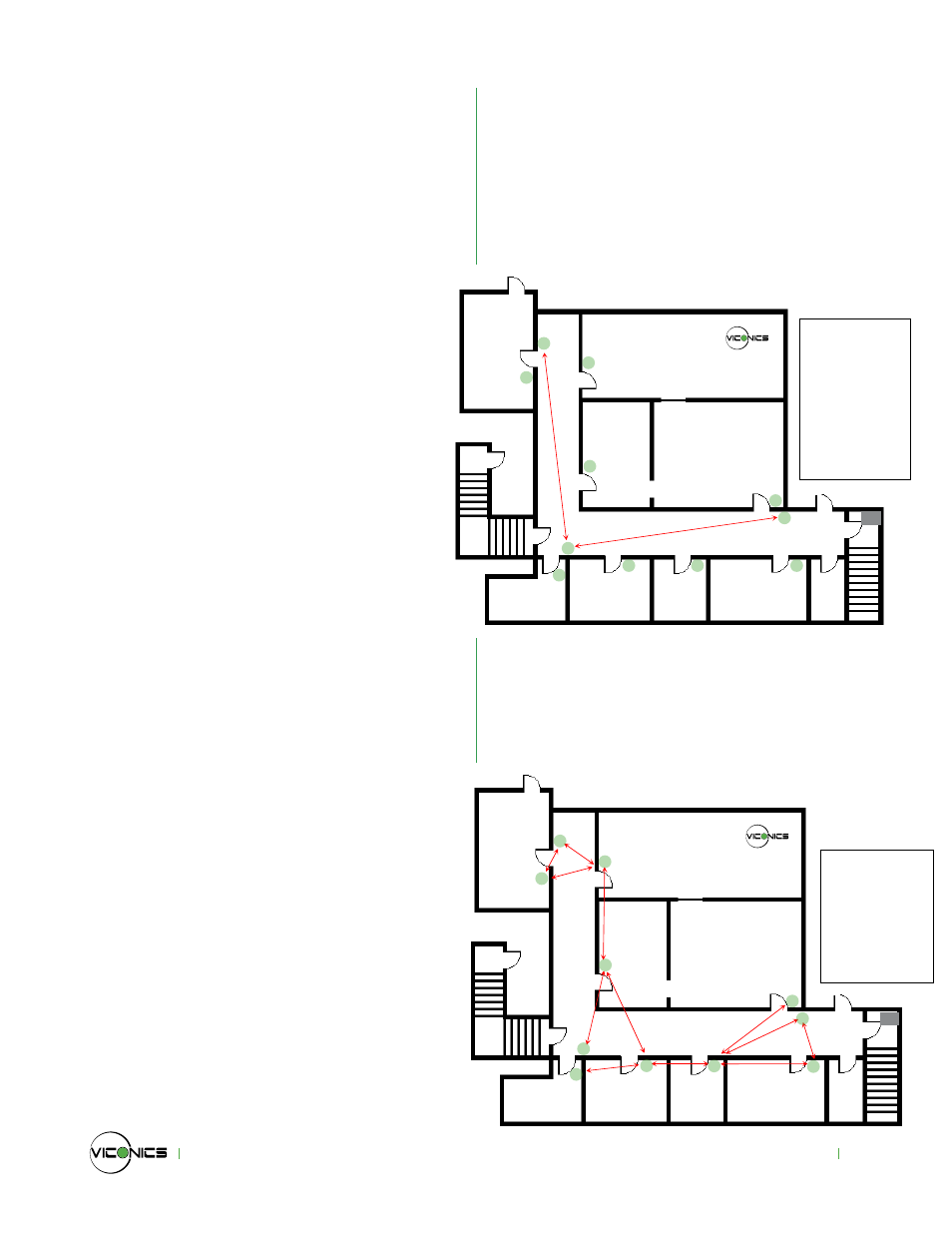
• With Clear line of sight deployment, (no physical
obstacles between 2 communicating controllers)
the maximum distance between each controller is a
maximum of 100 feet or 30 Meters (fig. 1).
Non-clear line of sight deployment
• The maximum non-clear line of sight distance
between controllers for gypsum wall partitions
which may include metal stud framing is a maximum
of 50 feet or 15 meters (fig. 2).
t
t
t
t
t
t
t
t
t
t
t
Beyond Comfort
G
Line of sight
distance
between 2
nodes is a
maximum
of 100 feet
(30 M)
Fig. 1
t
t
t
t
t
t
Beyond Comfort
t
t
t
t
t
G
Maximum
50 feet
(15 M)
between 2
controller
nodes
Fig. 2