Installation guide, Figure 2, Figure 1 function and led indicators – Viconics SED-CMS-P (ZigBee Pro) Installation Guide User Manual
Page 4: Ceiling mounted sensor, Install ceiling motion sensor, Device function
Ceiling Mounted Sensor
Installation Guide
4
© 2
01
4 V
ic
on
ic
s. A
ll r
ig
ht
s r
es
er
ve
d.
Viconics Technologies Inc. | 9245 Langelier Blvd. | St.-Leonard | Quebec | Canada | H1P 3K9 | Tel: (514) 321-5660 | Fax: (514) 321-4150
028-6077-00 www.viconics.com | [email protected] October 2014
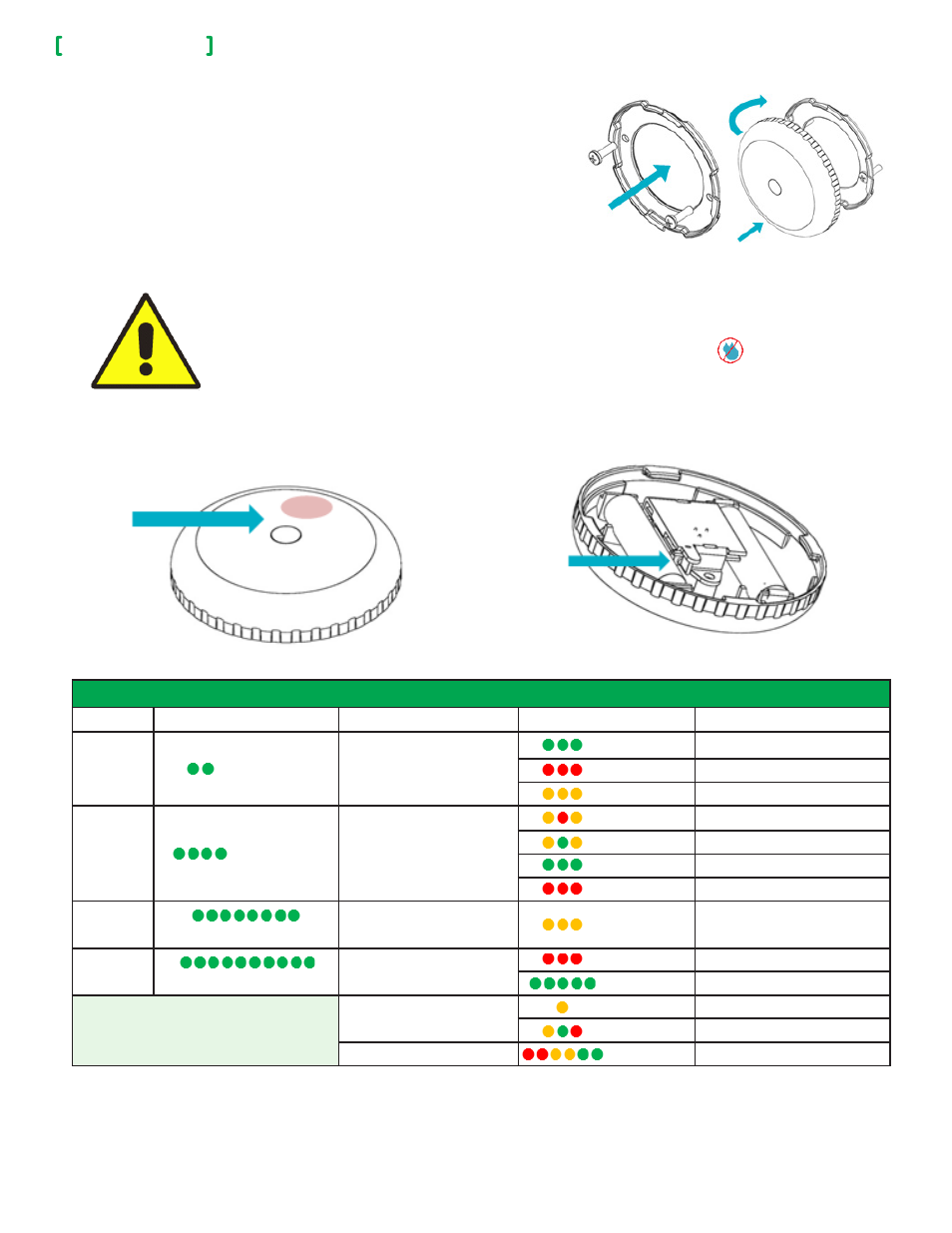
INSTALL CEILING MOTION SENSOR
1. Observe Sensor placement conditions before you install Sensor. Refer to
"Sensor Placement" on page 2.
2. Secure Mounting Plate to overhead surface with two screws (Figure 1).
NOTE: ensure screws are tight and Mounting Plate does not move easily. Do
not torque screws.
3. Set Sensor Housing assembly on Mounting Plate (Figure 2).
4. Rotate Sensor Housing assembly clockwise until it locks in place.
NOTE: ensure Sensor Housing assembly fits snugly to Mounting Plate.
5. Test Ceiling Motion Sensor. Refer to "Verify Sensing Motion" on page 3.
DEVICE FUNCTION
Figure 2
•
Always test Device before leaving job site.
•
Avoid installing Device directly on metal surfaces. Installation on metal can reduce transmission range.
•
Ensure Device is installed in dry location away from water, moisture, and rain.
Figure 1
Function and LED Indicators
BUTTON
LED
ACTION
LED
DESCRIPTION
2 times
GG
Network Status
GGG
Joined
RRR
Not Joined
YYY
Re-Join in Process
4 Times
GGGG
Network Join
YRY
Searching for Network
YGY
Device Being Configured
GGG
Device Joined
RRR
Device Failed to Join
8 Times
GGGGGGGG
Forced Re-Join
YYY
Re-Join, Searching for Parent
10 Times
GGGGGGGGGG
Network leave and join a
new Network
RRR
Leave if Joined
GGGGG
Defaults Restored
G = Green
Y = Yellow
R = Red
No Action
Y
Wrong Button Press
YGR
Device Busy
Power Up
RRYYGG
Mounting Plate
Sensor Housing
LED
Button