6typical applications – Viconics VT7300 Installation Manual (First Release 1000 Series) User Manual
Page 6
6
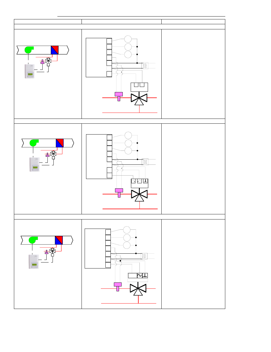
Typical applications
Schematic Wiring Settings
2 pipe system cooling and/or heating ( VT7300A1000, VT7300C1000 & VT7305C1000 ) On / Off N.C. actuator
Mandatory
• Pipe no = 2 pipes
• CntrltTyp = On/Off
• Fan Menu = 0 (L-M-H)
• FL time = as per actuator
If cooling only set::
• SeqOpera = 0 Cooling only
If heating only set::
• SeqOpera = 1 Heating only
If heat / cool auto-changeover
with a local water temperature
sensor set:
• SeqOpera = 0 Cooling only
• UI3 = COS
2 pipe system cooling and/or heating ( VT7300C1000 & VT7305C1000 ) Floating actuator
Mandatory
• Pipe no = 2 pipes
• CntrltTyp = Floating
• Fan Menu = 0 (L-M-H)
• FL time = as per actuator
If cooling only set::
• SeqOpera = 0 Cooling only
If heating only set::
• SeqOpera = 1 Heating only
If heat / cool auto-changeover
with a local water temperature
sensor set:
• SeqOpera = 0 Cooling only
• UI3 = COS
2 pipe system cooling and/or heating ( VT7300F1000 & VT7305F1000 ) Analog actuator
Mandatory
• Pipe no = 2 pipes
• Fan Menu = 0 (L-M-H)
• RA/DA = as per actuator
If cooling only set::
• SeqOpera = 0 Cooling only
If heating only set::
• SeqOpera = 1 Heating only
If heat / cool auto-changeover
with a local water temperature
sensor set:
• SeqOpera = 0 Cooling only
• UI3 = COS
0 to 10
Vdc
UI3 COS
0 V~ Com
24 V~ Hot
AO1
Optional supply water
temperature sensor
Fan-L
Fan-M
Fan-H
High
Med
Low
24 Vac fan relays
Modulating Analog
Valve Cooling and/or Heating
Room Temperature
Control Thermostat
3 Speed fan
Modulating Floating
Valve Cooling and/or Heating
Room Temperature
Control Thermostat
3 Speed fan
Optional supply water
temperature sensor
UI3 COS
24 V~ Com
24 V~ Hot
BO1 Open
BO2 Close
Fan-L
Fan-M
Fan-H
High
Med
Low
24 Vac fan relays
Normally Closed On/Off
Valve Cooling and/or Heating
Room Temperature
Control Thermostat
3 Speed fan
Optional supply water
temperature sensor
UI3 COS
24 V~ Com
24 V~ Hot
BO2 N.C.
Fan-L
Fan-M
Fan-H
High
Med
Low
24 Vac fan relays