Vt8600, Vt8600 series installation guide, Series controller – Viconics VT8600 Installation Guide User Manual
Page 9: Remote wiring 3 sensors
VT8600 Series
Installation Guide
9
Viconics Technologies Inc.
|
9245 Langelier Blvd.
|
St.-Leonard
|
Quebec
|
Canada
|
H1P 3K9
|
Tel: (514) 321-5660
|
Fax: (514) 321-4150
028-0435-01
www.viconics.com
February 2015
©
2
01
5 V
ic
onic
s T
ec
hno
lo
gi
es
. A
ll r
ig
ht
s r
ese
rv
ed
.
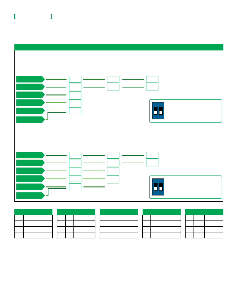
Wiring examples of 3 remote room sensors for averaging applications:
VT8600
Series Controller
2xS3010W1000 and 1xS3020W1000
Remote wiring 3 sensors
S2-1= Off, S2-2=On
SCom
RS
Aux
C
DI
SCom
RS
SCom
RS
VT8600
Series Controller
1xS3010W1000 and 2xS3020W1000
Remote wiring 3 sensors
S2-1= Off, S2-2=On
SCom
RS
Aux
C
DI
SCom
RS
Aux
C
DI
SCom
RS
Common
UI 20 - RS
B0 1 - AUX
C (Common)
UI 16
UI 17
Common
UI 20 - RS
B0 1 - AUX
C (Common)
UI 16
UI 17
Dip switch setting for 3 sensors
S2-1= Off, S2-2=Off
ON
1 2
Dip switch setting for 3 sensors
S2-1= Off, S2-2=Off
ON
1 2
Temperature vs. resistance chart for 10 Kohm NTC thermistor (R25°C = 10K
Ω±3%, B25/85°C = 3975K±1.5%)
ºC
ºF
Kohm
ºC
ºF
Kohm
ºC
ºF
Kohm
ºC
ºF
Kohm
ºC
ºF
Kohm
-40 -40 324.3197
-20 -4
94.5149
0
32 32.1910
20 68 12.4601
40
104
5.3467
-35 -31 234.4009
-15 5
71.2430
5
41 25.1119
25 77 10.0000
45
113
4.3881
-30 -22 171.3474
-10 14 54.1988
10
50 19.7390
30 86 8.0694
50
122
3.6202
-25 -13 126.6109
-5
23 41.5956
15
59 15.6286
35 95 6.5499
55
131
3.0016
or
or