Vt8600 series installation guide, Installation – Viconics VT8600 Installation Guide User Manual
Page 2
Viconics Technologies Inc.
|
9245 Langelier Blvd.
|
St.-Leonard
|
Quebec
|
Canada
|
H1P 3K9
|
Tel: (514) 321-5660
|
Fax: (514) 321-4150
028-0435-01
www.viconics.com
February 2015
VT8600 Series
Installation Guide
2
©
2
01
5 V
ic
onic
s T
ec
hno
lo
gi
es
. A
ll r
ig
ht
s r
ese
rv
ed
.
• If replacing an existing thermostat, label wires before removal
of Controller.
• Electronic controls are static sensitive devices. Discharge
yourself correctly before manipulating and installing Controller.
• A short circuit or wrong wiring may permanently damage
Controller or equipment.
• All VT8600 ® series controls are designed for use as operating
controls only and are not safety devices. Tampering with the
devices or unintended application of the devices will result in a
void of warranty.
• This device must be installed to provide a separation distance
of at least 8 in (40 cm) from all persons and must not be
collocated or operating in conjunction with any other antenna
or transmitter.
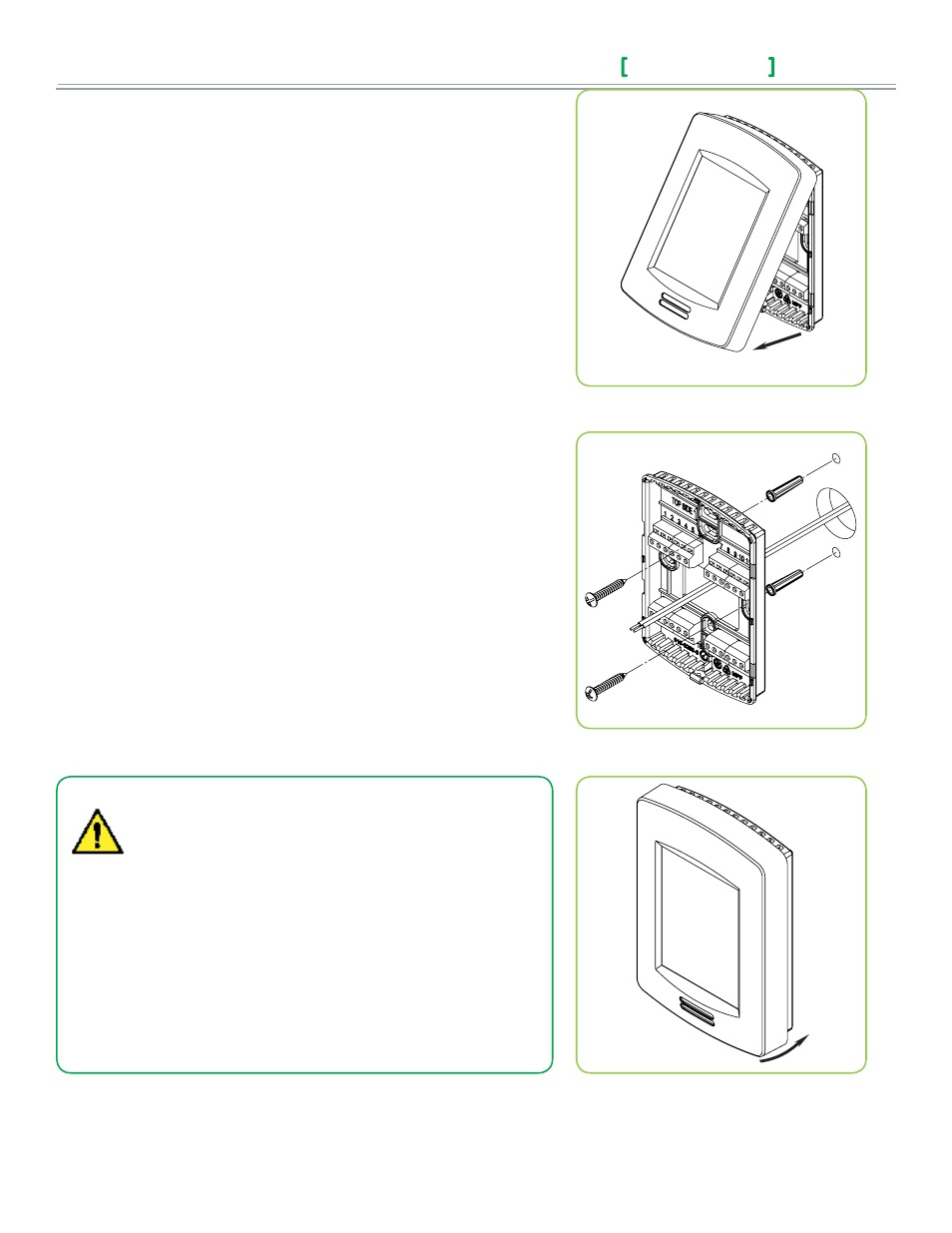
Figure-1 Open the cover
Figure-2 Install the base
Figure-3 Reinstall cover
INSTALLATION
Preparation
• Remove the security screw (if any) on the bottom of the Terminal Equipment
Controller cover.
• Open unit by pulling on bottom side of the Terminal Equipment Controller
(Fig. 1).
• Read FCC ID and IC label installed in cover before installing any wireless
product.
• Ensure correct side of base faces up.
Location
1. Do not install on outside wall.
2. Do not install in areas with direct heat source.
3. Do no install near any air discharge grill.
4. Do not install in areas exposed to direct sunlight.
5. Ensure Controller has sufficient air circulation.
6. Ensure wall surface is flat and clean.
Installation
1. Pull cables 15 cm ( 6” ) out from wall.
2. Align base and mark location of two mounting holes on wall.
3. Install anchors in wall.
4. Insert cable in central hole of base.
5. Insert screws in mounting holes on each side of base.
6. Strip each wire 1/4” ( 0.6 cm) from end.
7. Insert each wire and screw according to wiring chart (next page).
8. Gently push excess wiring back into hole.
9. Gently align cover to top of base and snap in place from bottom.
10. Install security screw.