Operation – USL XTD-33 User Manual
Page 21
XTD-33 I
NSTRUCTION
M
ANUAL
U
LTRA
★
S
TEREO
L
ABS
, I
NC
.
- 21 -
Operation
Normal Operation
•
Power Switch - During the first 15 seconds after the XTD is turned on,
it will function in the Backup Mode and audio signals will be pro-
cessed by the analog crossover. Once the system has stabilized and
the firmware programs have been loaded, it will set itself to the
configuration determined by the speaker selection switches.
•
Power LED - Should be green indicating normal operation.
•
Crossover Presets - DO NOT ADJUST WITH THE UNIT ON (see
Alignment Section). The unit only recognizes changes when it is first
turned on. Changing the switches while the power is on may result in
an incompatible configuration that may not be noticed until the next
time the unit is turned on.
•
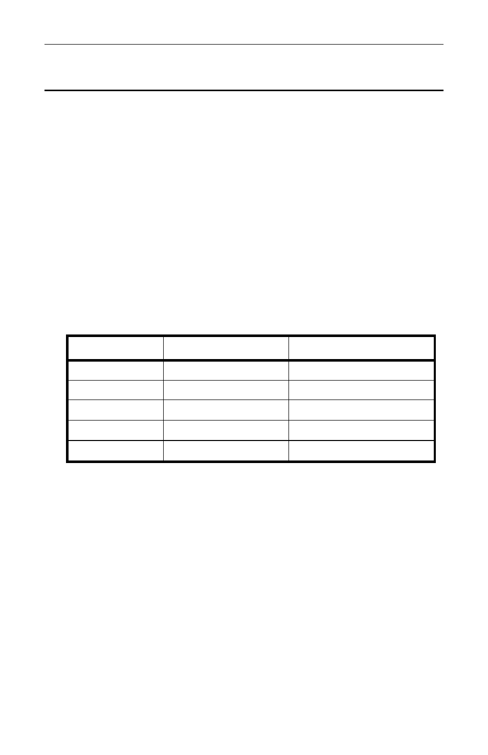
Signal Level LEDs - The three LEDs indicate the signal levels of the
three input channels to the XTD as shown in the chart below. Note:
0dB = 300mV rms
•
Output Signal Level Adjustment - Should be already set (see the
Alignment Section).
Bypass Operation
•
Backup power - If the primary Power Supply fails the Power LED will
be red, Contact USL. If the digital processing fails (or to check the
processing) turn the Power Switch Off and the unit will go into Bypass
mode, Contact USL
•
Backup Crossover Type (Two-or-Three-Way) - Should be already set
(see Alignment) Up (or On) is two-way; Down (or Off) is three-way.
Updating the Program and Crossover Files
Updating the XTD firmware requires special knowledge and training pro-
vided with update package, please contact USL.
Please make note of the firmware version number on the rear of the unit.
LED Color
Signal Level
Signal Measurement
Off
No Signal
< -54dB
Green
Signal present
-54dB to -0.5dB
Yellow
Reference level
-0.5dB to +0.5dB
Green
Signal present
+0.5dB to +23dB
Red
Clipping
> +23dB