Optional chassis grounding, Rear panel signal output connections, Balanced output – USL XTD-33 User Manual
Page 17: Unbalanced output, Xtd-33 i
XTD-33 I
NSTRUCTION
M
ANUAL
U
LTRA
★
S
TEREO
L
ABS
, I
NC
.
- 17 -
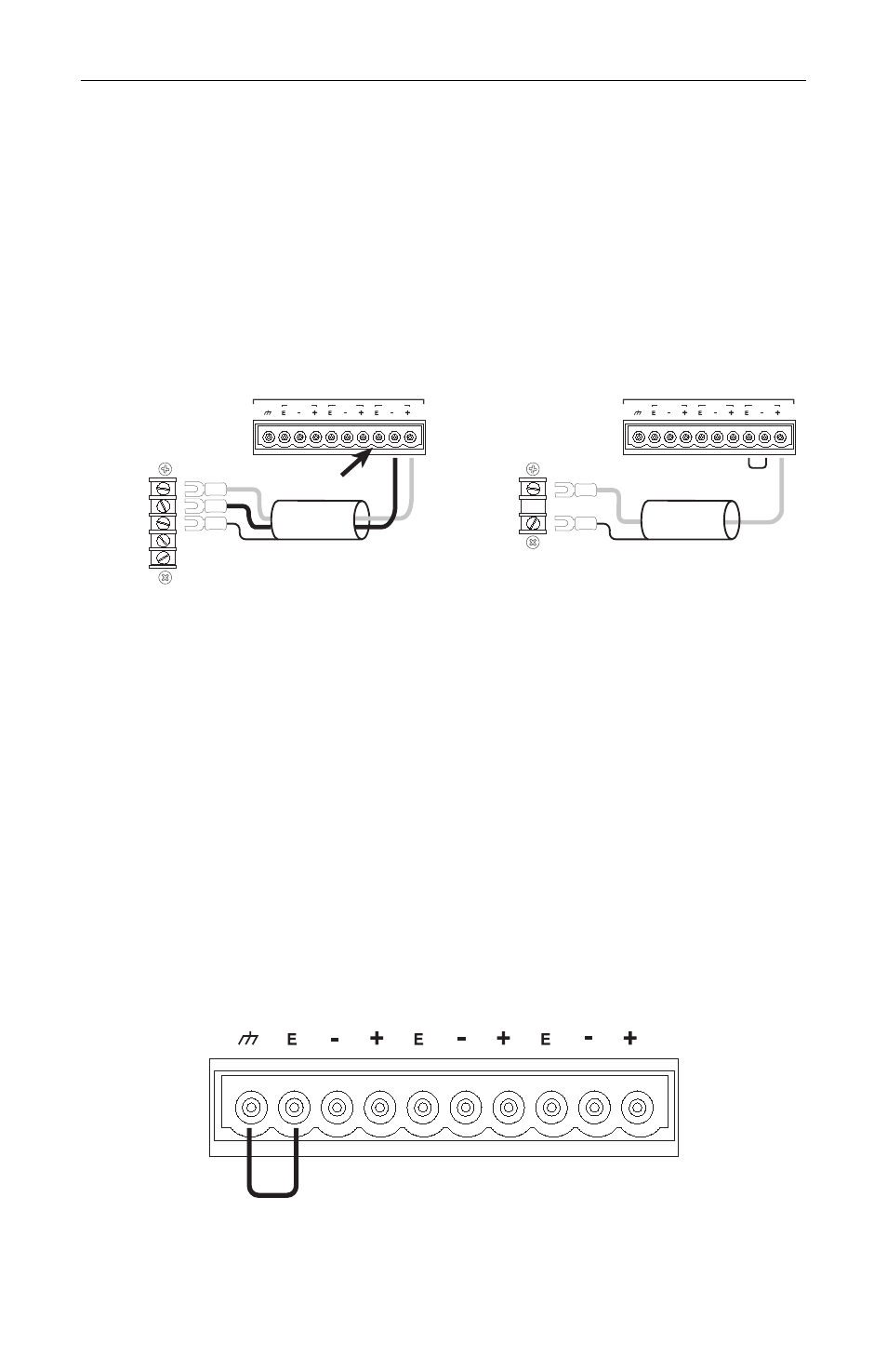
Rear Panel Signal Output Connections
Three-Way Crossover Connection - use all three output bands: Low, Mid, High
Two-Way Crossover Connection - use only Low and High bands
Balanced Outputs
For each band in each channel, connect the XTD positive output to the
positive input of the Amplifier. Connect the XTD negative output to the
negative input of the Amplifier. Connect the cable shield only to the Amplifier
signal ground to minimize hum due to ground loops
LEFT CHANNEL OUTPUTS
HIGH
MID
LOW
Channel 1
+
-
GND
NO SHIELD
CONNECTION
Balanced Output
LEFT CHANNEL OUTPUTS
HIGH
MID
LOW
Channel 1
+
GND
Unbalanced Output
Unbalanced Outputs
The outputs of the XTD use a solid state transformer simulator. BOTH
POSITIVE AND NEGATIVE OUTPUTS MUST BE CONNECTED SOME-
WHERE. (If your Amplifier does not have balanced inputs, the XTD negative
output needs to be connected to the XTD signal ground [“E”] by a short piece
of wire.) For each band in each channel, connect the XTD positive output to
the positive input of the Amplifier. Connect the XTD negative output to the
signal ground output (“E”) with a short piece of wire. Connect the cable shield
only to the Amplifier to minimize hum due to ground loops
Optional Signal to Chassis Grounding
If you wish to connect the Signal Ground (“E”) to the Chassis Ground, install
a jumper between the two left terminal block pins on only one of the terminal
blocks (any terminal block).
Optional Chassis Grounding