Top Flite TOPQ8414 User Manual
Page 2
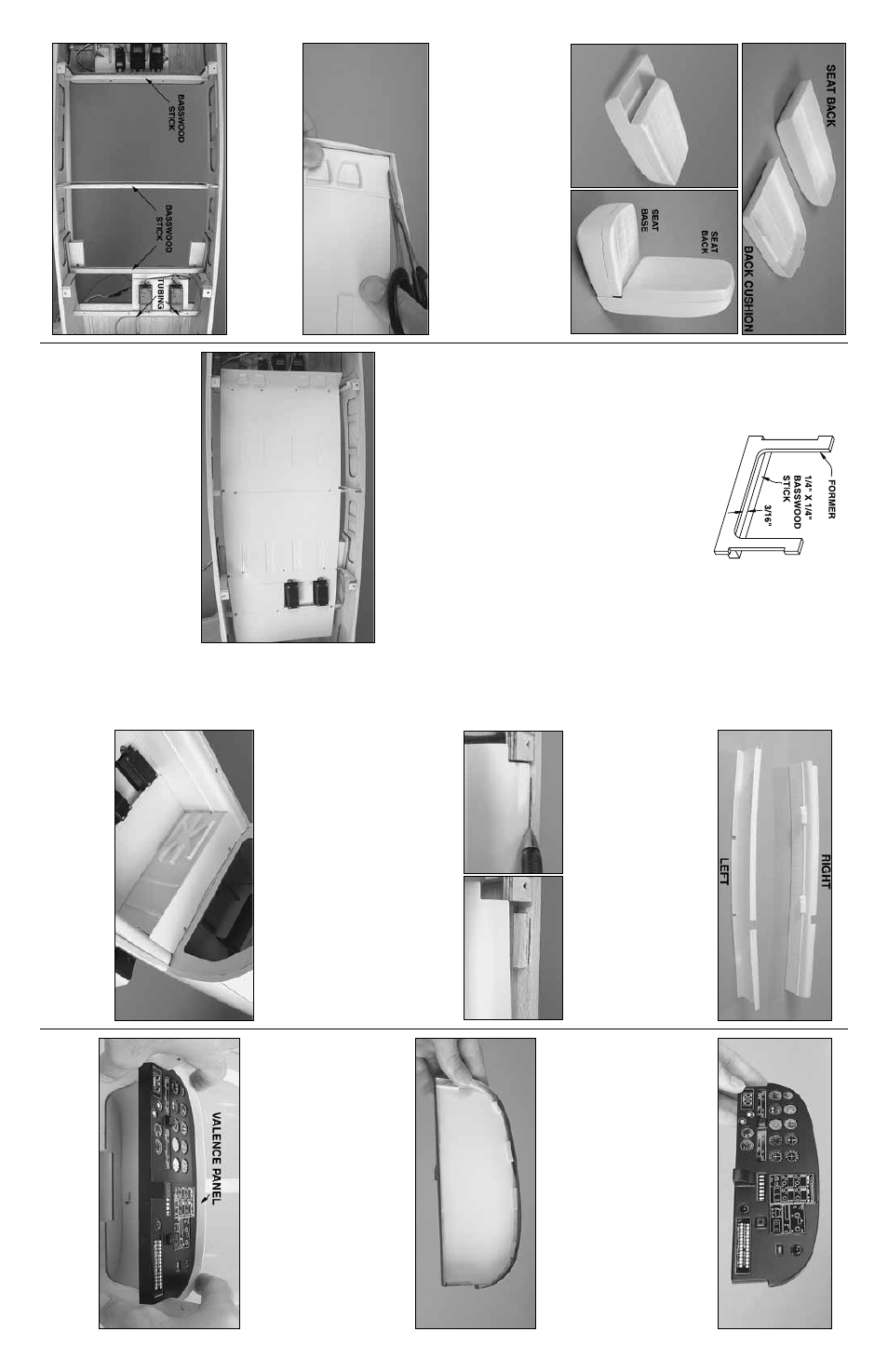
❏
3.
Cut out a seat bac
k and a bac
k cushion.
Glue the tw
o
pieces together
.
❏
4.
Glue the completed seat bac
k to the completed seat base
.
❏
5.
Mak
e three more seats the same w
a
y—he
y,
aren’t y
o
u
glad it’
s not a 747?
INST
ALL THE
FLOOR
❏
1.
Use cur
v
ed-tip plastic-cutting scissors to cut out the
coc
kpit floor
.
After cutting, the floor should be a flat sheet
with no lip around the edges
.
T
rue the edges of the coc
kpit
floor b
y
sanding.
❏
2.
Glue three 1/4" x 1/4" [6 x 6mm] bass
w
ood stic
ks (not
supplied) across the cross member por
tion of f
o
rmers F3,
F4 and F5 as sho
wn.
Note that the top edge of each stic
k is
3/16" [5mm] abo
v
e
the top edge of each cross member
.
❏
3.
Glue pieces of lefto
v
er 3/16" [5mm] pushrod tubing to
the aft edge of the aft ser
v
o
r
ail to guide the air line coming
from the air tank.
❏
4.
As indicated in the instr
uction man
ual f
or the Arro
w
air
plane kit, cut notches in f
o
rmers F3, 4 and 5 f
o
r the ser
v
o
wires and the air lines
.
Also round the top of f
o
rmer F4 to
accommodate the coc
kpit sides
.
❏
5.
Bend the coc
kpit floor upw
ard at the molded in scr
ibe
line
, b
ut use care not to break it off
.
Reinf
orce both sides of
the seam with thin CA.
❏
6.
T
est fit the coc
kpit floor into the fuselage
.
Cut the floor
where necessar
y to accommodate the f
o
rmers and ser
v
o
s
.
When in position, the front of the floor should be e
v
en with
the front of f
o
rmer F3.
Dr
ill 1/16" [1.6mm] holes through floor
and the 1/4" x 1/4" [6 x 6mm] stic
ks y
ou glued to the f
o
rmers
for f
astening the coc
kpit floor with scre
ws
.
Also dr
ill holes in
aft ser
v
o r
ail.
Install a #2 x 3/8" [9.5mm] scre
w into each
hole as y
ou go
.
Some holes will ha
v
e
to be dr
illed from the
bottom of the stic
ks and up through the floor
.
A
v
oid dr
illing
holes where the scre
ws will interf
ere with the coc
kpit sides
or seats
.
INST
ALL
THE SIDES AND B
A
CK
❏
1.
Cut out the
left
and
right coc
kpit sides
.
T
rue the
edges with a bar sander
.
❏
2.
T
est fit one
, then the other coc
kpit side into the
fuselage
.Widen the notches as necessar
y to accommodate
an
y f
o
rmers or the canop
y mounting b
loc
ks
.
T
he bottom
edges of the coc
kpit sides should rest on the coc
kpit floor
.
❏
3.
Once an
y necessar
y adjustments ha
v
e
been made to
get the coc
kpit sides to fit, use thin CA to glue both sides to
the floor
.
❏
4.
Use a ballpoint pen to mar
k the r
ight main fuselage
str
inger in three locations along the front, bac
k and middle
of the top of the coc
kpit side
.
❏
5.
Glue three 1/4" x 1/4" x 1" [6 x 6 x 25mm] hardw
ood
stic
ks to the str
inger 1/64" [.5mm] belo
w each line
.
Note
:
The top of the coc
kpit sides m
ust rest appro
ximately
3/32" [2.4mm] belo
w the top edge of the fuselage main
str
ingers
.
This will pro
vide clear
ance betw
een the scre
w
heads and the canop
y fr
ame
.
❏
6.
Repeat the pre
vious tw
o steps f
or the left side of the coc
kpit.
❏
7.
Dr
ill 1/16" [1.6mm] holes through the top of the coc
kpit
sides into the hardw
ood stic
ks
.
T
empor
ar
ily mount the
coc
kpit sides with six #2 x 3/8" [9.5mm] scre
ws
.
❏
8.
Cut out the
cabin bac
k
.
T
est fit, then glue the aft edge
of the coc
kpit floor to the top of the lip on the bottom of the
cabin bac
k.
The same as w
as done f
or the sides
, glue
hardw
ood stic
ks to f
o
rm
er F6, then dr
ill tw
o more holes and
tempor
ar
ily scre
w the bac
k into position.
FIT THE
INSTR
UMENT
P
ANEL
❏
1.
Cut out the
instrument panel
—there should be an
appro
ximately 1/8" [3mm] lip all the w
a
y around.
❏
2.
Attach the instr
umentation decals using one of the
follo
wing tw
o methods:
A)
P
aint the instr
ument panel, then cut out each instr
ument
from the decal sheet and stic
k it to the front of the panel.
B)
Use a hob
b
y
knif
e and a rotar
y
tool to cut all of the
instr
uments from the panel.
T
rue an
y str
aight edges with
a small hob
b
y
file
.
T
rue circular holes with a piece of
sandpaper wr
apped around a do
w
el or a br
ass tube
.
P
aint the instr
ument panel.
After the paint dr
ies
, attach
the decal sheet, intact, to a plastic sheet.
Cut out the
sheet, then glue it to the bac
k of the instr
ument panel.
Use small balsa stic
ks to securely hold the sheet to the
bac
k of the panel.
❏
3.
Cut out the
v
alence panel
.
T
est fit the v
alence panel
and the instr
ument panel inside the cabin top
.
Mak
e
adjustments f
or a good fit, b
ut do not glue it into the cabin
top until instr
ucted to do so
.
2
3