Plastic parts list detailing parts list – Top Flite TOPQ8402 User Manual
Page 2
GETTING STARTED:
Assembling and installing your scale cabin interior will probably
require minor adjustments and “tweaking” to fit your particular model.
This is because of variations in building technique, parts alignment
and glue fillets that may interfere with proper positioning of the parts.
A little patience is all that is required to obtain a good looking
installation. Trim parts a little at a time, checking the fit after each
adjustment. Remember, you can always remove material, but it’s
hard to put it back.
❏
1. Start by trimming all parts to the embossed “trim lines.” Be sure
to leave a 3/8" lip around the fuselage side panels to provide a
gluing surface for the floor. Use a hobby knife or scissors to “rough
cut” the parts. Then, sand the parts with a sanding block to straighten
the edges. You can evenly sand the edges by simply taping a sheet
of 220-grit sandpaper to your workbench. Then, work the part in a
circular motion while pressing down gently.
NOTE: Save all scraps of smooth plastic in case you need them later.
❏
2. Before fitting any of the parts in the fuselage cavity, you will first
need to modify some of the formers. You will need to cut and remove
the top portion of formers F3, F4, F5 and F6 that extend across the
width of the fuselage as shown in the sketch above. If you have not
already done so, you should also drill any holes for the retract air
tubes as well as cut notches for the servo wires.
❏
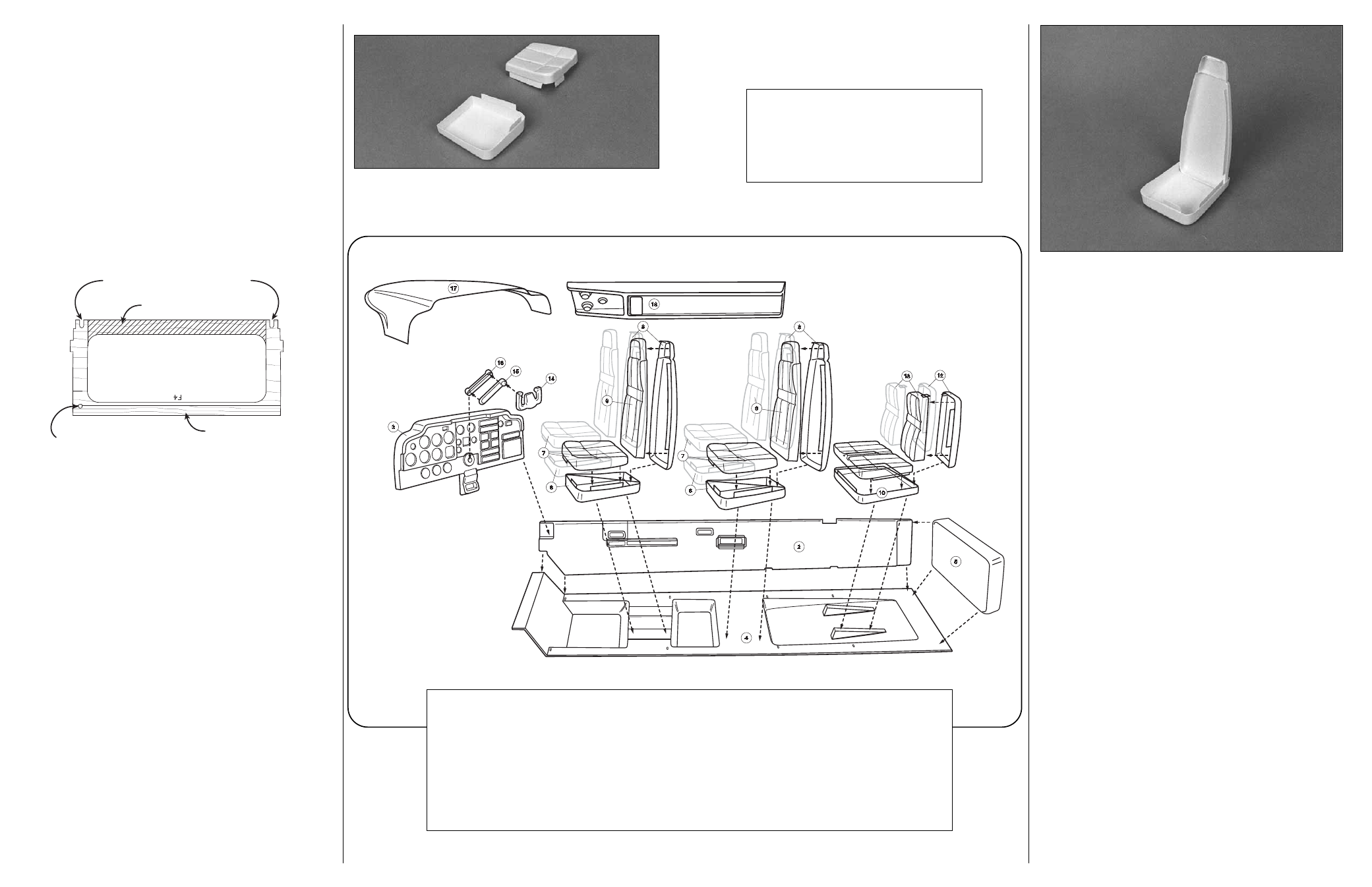
3. Refer to the exploded drawing to see how the parts fit together.
On the floor and side panels you will note several notches that must
be cut out to allow the floor to fit around the fuselage formers.
Without using any glue (and in the following order), fit the floor, sides
and aft bulkhead into the fuselage cavity. Make any adjustments
needed for a good fit.
❏
4. Place the cabin top on the fuselage and mark the crutch where
the instrument panel will be positioned. It is important to accurately
mark the position so that the instrument panel will mate properly with
the side panel when the cabin top is installed. The exploded view
shows the area that the instrument will slide into.
NOTE: If you have not already done so, we recommend that you glue
some reinforcing basswood sticks across the bottom of formers F4
and F6. There was extra 1/4" x 3/8" x 36" material included in the
Bonanza kit for this purpose. You must also decide how you will
attach the forward portion of the floor (the part that covers the servo
area.) We recommend some balsa stick scraps be used for this
purpose. This area can be easily accessed from the wing opening.
❏
5. When you are satisfied with the fit of the primary cabin parts,
remove them from the model and set them aside until it’s time
to paint.
ASSEMBLE THE SEATS:
❏
1. Check the glue tabs on all of the seat fronts and backs to insure
that they align and fit properly. Trim and adjust them as needed. Do
the same for the seat tops and bottoms.
SLOTS FOR SERVO WIRES
REMOVE THIS AREA
BASSWOOD RAIL
1/8" AIR TUBE HOLE
❏
2. Starting with a front seat, insert the seat back onto the seat
bottom. Hold the parts in position with a piece of masking tape. The
seat back should angle toward the rear of the cabin by a few
degrees. Glue the seat back in position by “wicking” a few drops of
thin CA into the joint along the bottom and sides. Remove the tape
after the CA has cured.
❏
3. Tape the seat cushion to the bottom half of the seat at a couple
of places. When properly aligned, use thin CA to glue the parts
together. Remove the tape after the CA cures. Use the same
technique to add the seat back cushion.
❏
4. Assemble the remaining front seat, the two center seats and the
rear bench seat the same way.
❏
5. Use plastic model seam putty or automotive body filler to cover
all of the joints. When the filler has cured, wet sand it smooth with
220 or 340-grit sandpaper.
❏
6. Seat back pockets can be made from elastic thread and thin
cloth glued into position.
PAINTING AND DETAILING
❏
1. Before painting, thoroughly clean the parts with rubbing
alcohol, then allow them to dry completely.
❏
2. Spray all parts with white enamel primer. Be sure to use a
primer that is compatible with styrene plastic (Top Flite
®
LustreKote
™
is NOT recommended). Lightly wet sand the parts with sandpaper
and allow them to dry. Repeat the priming and sanding process if
needed.
❏
3. Paint all of the parts with model enamel. Apply the lightest color
of paint first. Use a 1/2" wide camel hair brush (or an artist’s air
brush) to obtain the smoothest finish. The bases on the floor (that the
seats are mounted to) should be painted flat black.
❏
4. Due to the curvature of the floor pans, scale looking carpeting is
very difficult to simulate. It is best done with a rough texture paint.
3
6
7
6
7
9
9
16
17
15
14
8
18
8
13
10
5
2
4
12
1
...........1 ............Side panel – left (not shown)
2
...........1 ............Side panel – right
3
...........1 ............Instrument panel
4
...........1 ............Floor
5
...........1 ............Aft bulkhead
6
...........4 ea. ......Lower front and middle seats
7
...........4 ea. ......Front and middle seat cushions
8
...........4 ea. ......Front and middle seat back – rear half
9
...........4 ea. ......Front and seat back – front half
0
...........1 ea. ......Lower rear seat
-
...........1 ea. ......Rear seat cushions
=
...........1 ea. ......Rear seat back – rear half
q
...........1 ea. ......Rear seat back – front half
w
..........2 ea. ......Control yoke
e
...........1 ea. ......Yoke arm – front half
r
...........1 ea. ......Yoke arm – rear half
t
............1 ea. ......Glare shield
y
...........1 ea. ......Roof console
PLASTIC PARTS LIST
DETAILING PARTS LIST
– NOT SHOWN –
1 yd. .....Dressmakers’ elastic – seat belts
6 ea......Small head pins – dash knobs/buttons
3 ea......Large head pins – throttle/mixture knobs
1 ea......Instrument panel decal