Toa CR-413-6 User Manual
Page 13
13
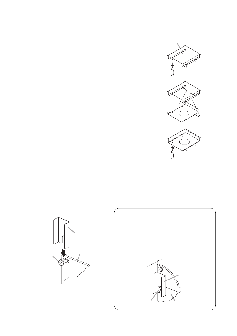
4.3. BU-412 Blower Unit (option) Installation
The installation instructions are also printed on the BU-412 itself.
Step 1. Loosen 4 screws inside the top panel.
(No need to remove them.)
Step 2. Align the BU-412's front notches with the loosened front
screws, and rear notches with the rear screws.
Step 3. Tighten 4 loosened screws to secure the BU-412.
4.4. Screw Cover Installation
Install the screw covers after installation completion of all the components.
Eight screw cover fittings (4 each on both sides) are supplied with the unit.
Step 1. Loosen any rack mounting screw that holds the component, then insert the supplied screw cover
fitting into the gap exposed.
Top panel
Screw cover fitting
(accessory)
Rack mounting
screw
Component
Notes
The component's front panel thickness may differ
depending on the model. In such cases, insert a
spacer between the screw cover fitting and
component’s front panel to align the height of all
screw cover fittings from the components’ panel
surfaces.
Height of the screw cover fitting
from the panel surface
Screw cover fitting
(accessory)
Rack mounting screw
Component