Installation and connection, Installation procedures – Toa W-912A Service Manual User Manual
Page 9
9
7. INSTALLATION AND CONNECTION
Installing this amplifier requires the optional back box, which is Model BX-9F for flush mounting in any 4 inch
wall and Model BX-9S for surface mounting.
Fix the back box first before installing the amplifier.
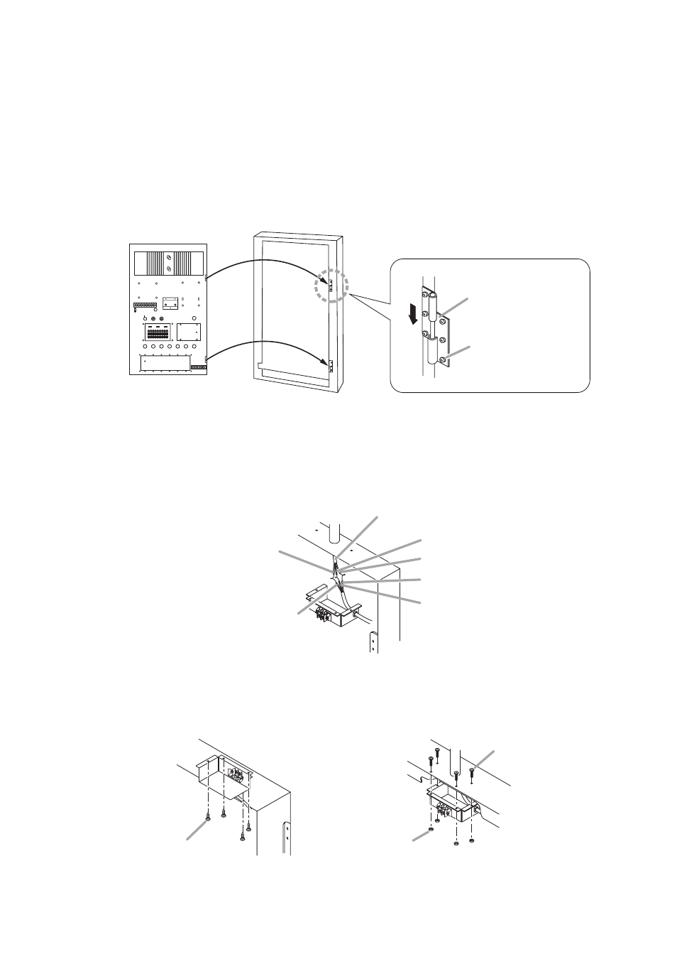
7.1. Installation Procedures
Step 1. Attach the supplied hinges to the back box using the 6 supplied M3 x 6 machine screws.
Step 2. Fix the amplifier to the back box by inserting the amplifier bolts into the hinges as illustrated.
Step 3. Connect the power cable.
Be sure to make proper cable connections according to color cording of the power cable.
After connection completion, wrap insulation tape around cable joints and put them in a junction box.
Step 4. Attach the junction box to the back box using the supplied screws as shown below.
The BX-9F differs from the BX-9S in the way to attach the junction box to the back box.
From indoor wiring
Junction Box
BLACK
GREEN/YELLOW
GREEN
BLUE
BROWN
WHITE
Tapping screw 3 x 8
(accessory)
Flange nut for M3
(accessory)
Machine screw M3 x 10
(accessory)
[BX-9F]
[BX-9S]
INPUT 1
POWER
ON
250V 3A
250V 6A
OFF
OFF
MAX
INPUT 2
INPUT 3
AC FUSE
OFF
ON
LOW PASS
OFF
ON
HIGH PASS
OUT
63
125
250
500
1k
2k
4k
8k
16k
63
125
250
500
1k
2k
4k
8k
16k
IN
EQUALIZER
OUTPUT FUSE
COMPRESSOR
INPUT 4
INPUT 5
INPUT 6
MASTER
12
6
0
6
12
12
6
0
6
12
Amplifier
(main chassis)
Back Box
BX-9F or BX-9S
Hinge (accessory)
Machine screw M3 x 6
(accessory)