Toa SV-200MA User Manual
Page 4
133-21-505-00
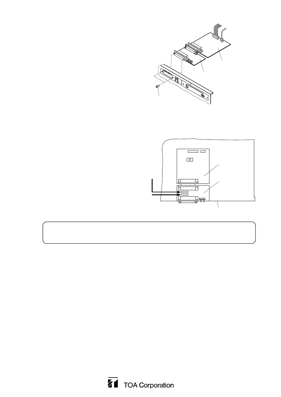
Step 7. Using the removed 2 hexagonal sleeves, mount the
SV-200MA assembly in the amplifier.
Hexagonal sleeve
SV-200M board
SV extension board
Step 8. Connect the flat cables to the SV extension board.
Be sure to correctly connect the flat cables between the following connectors:
VM CPU board's CN 7 – SV extension board's CN3
VM relay board's CN1001 – SV extension board's CN4
Note
Pay attention to the orientation of each cable so that
it's contact face touches the connector's contacts.
Step 9. Check the DIP switch on the SV-200M board again for correct setting. (Refer to the installation
manual for the VM-2120 and VM-2240.)
Step 10. Using the 4 rear panel screws and 6 side panel screws removed in Step 3, replace the amplifier
cover.
CN3
CN4
Rear panel
SV-200M
board
SV extension
board
From VM CPU board's CN 7
From VM relay board's CN1001
IMPORTANT
Ensure that all cables are correctly connected. Misconnection of the cables may cause the SV
extension board to fail.