Toa SV-200MA User Manual
Page 2
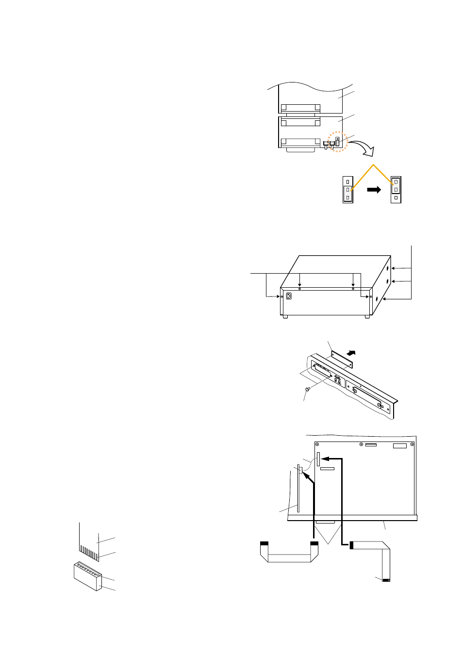
3. INSTALLATION
Step 1. Set the DIP switch on the SV-200M board referring to the installation manual for the VM-2120 and
VM-2240.
Step 3. Remove 4 screws on the amplifier rear panel and a
total of 6 screws on the sides to remove the cover.
Step 4. Detach the surveillance I/O blank panel on the
amplifier rear panel by removing 2 fixing snap rivets.
Surveillance I/O blank panel
Snap rivet
Step 2. JP1 on the SV extension board is a 3-pin jumper
header and its short circuit socket is normally set to A
position. If you need to bypass the external attenuator
not only on all-zone broadcast but also individual
zone broadcast, set the socket to B position.
Note
External attenuator bypass function with individual
zone broadcast can be used only with 4-wire
attenuators.
This function basically cannot be used with
BGM/Paging function.
Step 5. Make connections of the supplied flat cables.
5-1 Remove the flat cable connected between the VM
CPU board's CN7 and the VM relay board's CN1001
of the VM amplifier.
5-2 Connect the supplied 2 flat cables to CN7 and to
CN1001, respectively.
Rear panel
CN7
CN6
VM relay board
For VM relay board
VM CPU board
For VM CPU board
CN1001
Remove
5
-1
5
-2
Contact face
Flat cable
Contact face
Contact
On-board connector
[Orientation of the flat cable]
Note
Pay attention to the orientation of the cable so that it's contact face touches the connector's contacts.
AB
SV-200M board
SV extension board
JP1
A position
(Factory-preset)
B position
Short circuit socket
A
B
A
B
Side: M4 x 8 machine screw ..... 3 pieces each
Rear: M3 x 6 machine screw
and M3 plain washer ..... 4 pieces