Setup modes, Display setup mode, System setup mode – TeeJet BoomPilot User Manual
Page 2: Boom offset direction, Boom offset distance, Display setup screen, Setup screen, Delay on, Delay off, Overlap
GPS
GPS
DGPS
ALL ON
AUTO
MAN
BoomPilot
ESC
6.0
MPH
AUTO
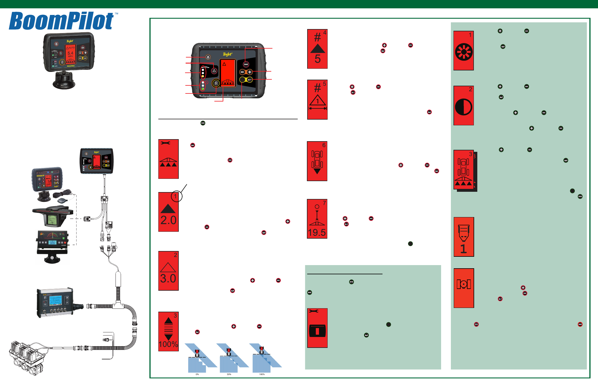
NuMBeR Of BOOM seCTIONs
The number of available boom sections is 1 to 6 or 1 to 15
depending upon which smartCable is detected. enter the
number of boom sections that are active in the system (1 to
15 sections). Use the Plus and Minus keys to adjust
the value. Press the enter key to accept the changes and
advance to the Boom section Widths setting.
BOOM seCTION WIdThs
enter the width for eACh boom section in inches (cm). use
the Plus
and Minus
keys to adjust the value. Press
the enter key to advance to the next Boom section Width
setting. When facing forward, the boom sections are ordered
from left to right along the boom. The boom section width
range is 0 to 1969 inches (0 cm to 50 m). The minimum rec-
ommended width is 39 inches (1 m). Press the enter key
to accept the changes to the last boom section and advance
to the Boom Offset direction setting. Individual boom section
widths can be set to different widths.
BOOM OffseT dIReCTION
A BACkWARd selection (as shown) indicates the boom is
located behind the GPs antenna as the vehicle moves in a
forward direction. A fORWARd selection indicates the boom
is located in front of the GPs antenna as the vehicle moves
in a forward direction. use the Plus
and Minus
keys
to adjust between forward or Backward. Press the enter
key to accept the changes and advance to the Boom Offset
distance setting.
BOOM OffseT dIsTANCe
Define the distance from the GPS antenna to the boom in
decimal feet (decimal meters). The boom offset distance
range is 0 to 164 decimal feet (0 to 50 decimal meters).
in the
example shown, 19.5 feet equals 19 feet 6 inches. use the
Plus and Minus keys to change the value. Press the
enter key to accept the changes.
Once the final setting has been entered and saved, the screen
will return to the initial BoomPilot setup screen. If no addition-
al changes are required, press the escape
ESC
key and exit to
Operation Mode.
dIsPLAY seTuP MOde
Press the setup Mode key until the initial display setup Mode screen
appears. To return to the BoomPilot setup Mode, press the setup Mode
key again.
dIsPLAY seTuP sCReeN
This is the initial display setup screen. setup screens
will time out after 10 seconds of inactivity (changes will be
saved). After time out, the screen will go back to Operation
Mode. Pressing the escape
ESC
key will also exit the user
from display setup Mode without saving any changes.
Press the enter key to advance to the display Bright-
ness setting.
sYsTeM seTuP MOde
seTuP sCReeN
This is the initial BoomPilot Pro setup screen. Press the en-
ter key to advance to the delay On setting. setup screens
will time out after 10 seconds of inactivity (changes will be
saved). After time out, the screen will go back to Operation
Mode. Press the escape key to exit from setup Mode with-
out saving any changes.
deLAY ON
delay On functions as a “look ahead” for timing the boom sec-
tion valves to switch on exactly when entering an area that
has not been applied. delay On time is established in sec-
onds and tenths of seconds. If the boom turns on too soon
when entering an un-applied area, decrease the delay On
setting. If the boom turns on too late when entering an un-
applied area, increase the delay On setting. use the Plus
and Minus keys to adjust the value. The delay On Time
range is 0.0 - 10.0 seconds. Press the enter key to accept
the changes and advance to the delay Off setting.
deLAY Off
delay Off functions as a “look ahead” for timing the boom sec-
tion valves to turn off exactly when entering an area that has
been applied. If the boom turns off too soon when entering
an applied area, decrease the delay Off setting. If the boom
turns off too late when entering an applied area, increase the
delay Off setting. The delay time is established in seconds
and tenths of seconds. use the Plus and Minus keys
to adjust the value. The delay Off Time range is 0.0 - 10.0
seconds. Press the enter key to accept the changes and
advance to the Overlap setting.
OVeRLAP
Overlap determines the amount of overlap that is allowed
when the boom sections are turned on and off. select the per-
cent of overlap from three pre-determined settings (0%, 50%,
and 100%) using the Plus and Minus keys. Press the
enter key to accept the changes and advance to the Num-
ber of Boom sections setting.
The BoomPilot
TM
is an automatic boom section control de-
vice that features 6 sections of control (up to 15 sections op-
tional). Overlap is minimized and applicator fatigue is greatly
reduced.
sMartCable - The smartCable is the link between the ex-
isting rate controller, the boom valves, and the BoomPilot. It
allows the BoomPilot to automatically control the boom sec-
tion valves.
setup MOdes
dIsPLAY BRIGhTNess
The Plus and Minus keys can be used to change
the brightness levels of the display screen. Press the
keys until the desired brightness is established. Press
the enter key to advance to the display Contrast
setting.
dIsPLAY CONTRAsT
The Plus and Minus keys can be used to change
the contrast levels of the display’s background. Press
the enter key to advance to the display Background
setting.
NOTE: The Plus and Minus keys control con-
sole brightness levels during Operations
modes. However, if GPS signal is not re-
ceived, the Plus and Minus keys will
control the contrast level.
dIsPLAY BACkGROuNd
The Plus and Minus keys toggle between light
and dark backgrounds. Press the keys until the desired
background is established. Press the enter key to
accept the changes.
Once the final setting has been entered, the screen will
return to the initial display setup Mode screen. If no ad-
ditional changes are required, press the escape
ESC
key
and exit to Operation Mode or press the setup Mode
key again to enter into BoomPilot system setup Mode.
COM PORT seTuP
The COM Port can be customized to send dGPs data out
or accept external dGPs. The BoomPilot console does not
contain an internal GPs receiver. Therefore, this setting
must remain set to “0” so that external GPs data can be
received.
GPs seTuP
GPs setup can be customized to accept “ANY” available
source transmission (either uncorrected or differential),
“GPs” source transmissions (only uncorrected signals), or
“dGPs” source transmissions (only differentially corrected
signals). use the Plus
key to select “ANY,” “GPs,” or
“dGPs” and the Minus
key to revert backward. Press
the enter
key to accept the changes.
power must be
cycled to the console if this setting is changed.
Once the final setting has been entered, the screen will return to the initial
display setup Mode screen. If no additional changes are required, press
the escape key and exit to Operation Mode or press the setup Mode
key again to enter into BoomPilot setup Mode.
GPs Input
RS-232
TeeJet CAN
Remote swath
status switch
(Optional)
smartCable
Adapter harness
45-05573
TeeJet 844
Rate Controller
Valves
Remote Master
+12 sw
RAdAR Power
Battery
Controller
harness
Before starting the BoomPilot, make
sure the spray control is powered up,
the Master switch is set to the “On”
position, and the boom switches are
turned “Off”.
GPS
GPS
DGPS
ALL ON
AUTO
MAN
BoomPilot
ESC
12.0
MPh
MAN
Power
Increase/decrease
swath status Change
(selects modes)
GPs status Lights
Change Page
setup Mode
- press once for BoomPilot setup
- press twice for display setup
escape
enter
display
swath status Lights
Press the setup Mode key to enter into BoomPilot setup Mode.
Console Power
setup screens are numbered sequentially for ease of operation.
4
ANY
5