Combining line zones and assigning them to a phase – SmarTek Systems SVS-1 User Guide-Part B User Manual
Page 34
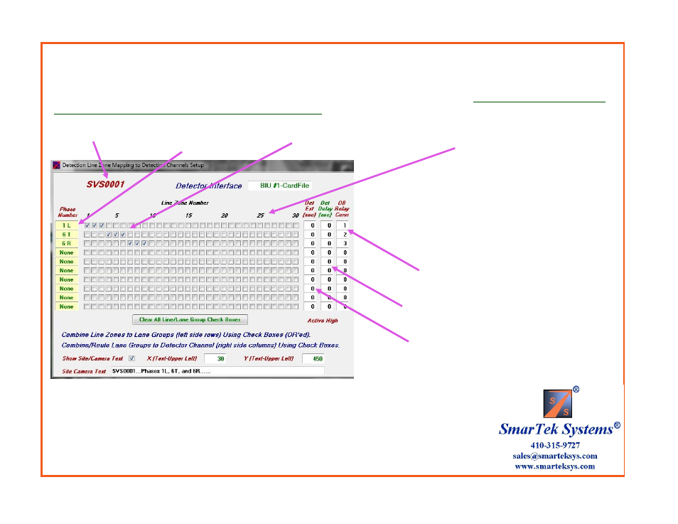
Combining Line Zones and Assigning Them to a Phase
Current Camera Channel ID
Phase Label
Check Boxes Specify Detection Line Zones
Assigned to Phase
Detection Line Zone Number
Specifies Mapping to Onboard Output Relay
Connector (1, 2, .., 10 0-No mapping to Onboard
Output Relay)
Specifies Phase Detection Extension
in Seconds
Specifies Each Phase Detection Delay
in Seconds
This display is used to combine and assign multiple Detection Line Zones to each Phase . The Detection Line Zone to Phase Mapping
Matrix has the Phase label on the vertical axis and the Detection Line Zone # on the horizontal axis.
Each checked box specifies that
a Detection Line Zone (column) will contribute to a Phase (row).
In this example Detection Line Zones 1, 2, and 3 are combined to form Phase 1L. Likewise, Line Zones
4, 5, and 6 are combined to form Phase 6T and Line Zones 7, 8, and 9 are combined to form Phase 6R.
Note: Intersection Phase labels may be changed by clicking in the upper/lower part of each Phase label
field. The L, T, R usage in the phase label indicates Left Turn, Thru, and Right Turn respectively..