Svs-1 – setup process overview – SmarTek Systems SVS-1 User Guide-Part B User Manual
Page 2
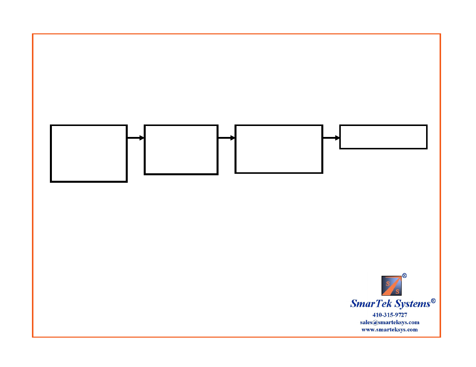
SVS-1 – Setup Process Overview
The primary function of the SVS Monitor and Setup Program is to provide the SVS-1 installer the means to quickly and
easily setup Detection Line Zones within each camera image field, group Detection Line Zones by assigning them to a
Phase, and then combine and route each Phase to the intersection controller.
Position Multiple
Detection Line Zones
in Each SVS-1
Camera Image and
Assign Them to an
Intersection Phase
Set Detection Line
Zone Parameters to
Achieve Required
Operating
Performance
Combine and Route
Phases to Output Relays
or Detector Channels for
Input to the Intersection
Controller
Save All Settings and
Send to the SVS-1
Step 2
Step 1
Step 4
Step 3
- Up to 30 Detection Line Zones
- Each line zone is directional
- Multiple line zones are placed
(drawn) in each lane and
assigned a phase number
-Line zones located in the left
turn lane are identified by the
phase number assigned to them
- Line Zone parameters are set to
default values providing excellent
performance in almost all
situations
- Line Zone parameters may be
“tuned” to deal with special
situations thus providing
maximum operating flexibility
- Phases are routed to output
relays or detector channels for
input to the intersection controller
- Each phase may have a unique
detection delay or extension applied
before being combined and routed
to the controller detector channel
input.
- Parameters are sent to each
SVS-1 camera channel’s non-
volatile memory to be stored and
used (even after power cycle or
system reset)
- Parameters may also be stored
in a user named PC file
- This 4 step process is repeated
for each SVS-1 camera channel