Installation requirements – Slant/Fin TRDV Series User Manual
Page 3
INTREPID TRDV
3
BOILER LOCATION
Provide a level, solid foundation for the boiler.
A. The foundation must be capable of supporting the weight of
the boiler when filled with water:
* Without tankless coil
B. The Intrepid boiler can be installed on both combustible and non-
combustible floors, but must NOT be installed on or above carpeting.
C. The Intrepid Boiler has full wet base sections which surround fire-
box for maximum heat absorption of burning fuel, and low floor
temperature.
D. If boiler is to be located over buried conduit containing electric wires
or telephone cables, consult local codes or the National Board of Fire
Underwriters for specific requirements.
CAUTION: NEVER BURN GARBAGE OR PAPER IN THE UNIT AND
NEVER LEAVE COMBUSTIBLE MATERIAL AROUND IT.
MINIMUM CLEARANCE
Provide accessibility clearance of 24" from surfaces requiring servicing (top
and front) and 18" on any side requiring passage. The boiler shall be
installed with the following MINIMUM clearances from combustible materials:
BACK AND SIDES- 6"
NOTE: Except in closets and alcoves, clearances above in (A) and
(B) may be reduced by providing forms of protection as specified in
NFPA 31, latest edition.
VENTING REQUIREMENTS
• The terminal shall not be closer than 3 feet above or 10 feet horizon-
tally from any forced air inlet into the building.
• The terminal shall not be closer than 4 feet below, 4 feet horizontally
or 1 foot above any door, window or gravity air inlet into the building.
• The terminal shall not be less than 3 ft from an inside corner of an “L”
shaped building.
• The terminal shall not be less than 7 ft above grade when located
adjacent to public walkways.
• The terminal shall not be less than 2 ft from an adjacent building.
• The terminal shall be located at a height not liable to blockage from
leaves, snow or other debris, at least 1 ft above grade or anticipated
snow line.
• The terminal shall be positioned so that flue gases are not directed
where they can jeopardize people, overheat combustible structures
or enter buildings.
• Vent terminal should be away from shrubbery or other obstructions
that would prevent free air flow to and from vent terminal. Do not ter-
minate vent under decks, stairways or car ports. When ever possible,
locations under windows should be avoided.
• Vent termination should not be mounted directly above or within 3 ft
horizontally from an oil tank vent.
VENT PIPING
A. The vent piping minimum bend radius is 12”.
B. Place metal strapping every 36” to support vent pipe and prevent it
from sagging.
C. Maximum wall thickness is 14”. Contact Slant/Fin Corp. for recommenda
tions in case of thicker wall.
D. Gases will form white plume in winter. Plume could obstruct window view.
E. Prevailing winds could cause freezing of condensate and water/ice buildup
on building, plants or roof.
F. Locate or guard vent to prevent accidental contact by people or pets, and
condensate from damaging exterior finish.
G.Do not terminate vent in window well, stairwell, alcove, courtyard, or other
recessed areas.
All venting kits must be double wall construction for the flue gas piping. Flex-
L and Field Controls are the two approved manufacturers for venting kits.
When installing the vent kits the manufacturers instructions must be fol-
lowed.
SEE TRDV VENTING INSTALLATION INSTRUCTIONS PUBLICATION
NO. TRDV40-V.
INSTALLING WATER TRIM
Notes: Jacket must be installed on boiler units prior to installation of trim.
I. WATER BOILER TRIM, see page 2 for tapping locations, and figures
1 and 2 for illustration of water boiler.
A. Pressure- temperature - Altitude gauge — use tapping no. 6.
B. High temperature limit — use tapping no. 7.
C. Operating control (if used) — use tapping no. 7.
D. Water relief valve — use tapping no. 3, piped full size to boiler.
E. Automatic air vent or compression tank tappings — if
used, install in tapping no. 2.
F.
Combustion safety control — mounted on burner.
PIPING
IMPORTANT:
Boilers are to be used with closed system. Any application
that uses steam or water from system, causes the introduction of a frequent
supply of fresh water into the boiler. This will cause damage to the boiler.
Use of heat exchangers will prevent this damage.
PIPING FOR WATER UNITS
NOTE: On knock down boiler only, jacket may be installed after supply and
return piping connection, but must be installed prior to adding trim.
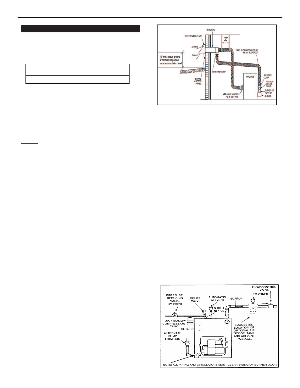
I. CIRCULATING SYSTEM
A. FORCED CIRCULATION hot water heating system: Use the top
tapping as supply tapping, and use the front or rear bottom
tappings for the return.
B. A FLOW CONTROL VALVE (See figure 4) will prevent gravity
circulation and usually is required when tankless heater is installed.
Boiler
Approximate Total Weight of Boiler
Size
Assembly, filled with water
TRDV-30
550*
Figure 4. Air Eliminating System
Figure 3. Typical Installation
INSTALLATION REQUIREMENTS