Slant/Fin TRDV Series User Manual
Page 10
10
INTREPID TRDV
TRDV-30-0.85
BF-5
0.85
3.21
0.65
70 W
Delavan
170
0
3.1
TRDV-30-1.00
BF-5
1.00
3.78
0.85
70 W
Delavan
140
0
4
TRDV-30-1.10
BF-5
1.10
4.16
0.85
70 W
Delavan
170
1
4
Boiler Model
Riello
Burner
Model
GPH
L/Hr
Size
(GPH)
Angle &
Type
Mfg.
Oil Pump
Pressure
Setting
“A”
Approx.
Head
Approx.
Air Band
Opening
Firing Rate No. 2 Oil
Nozzles
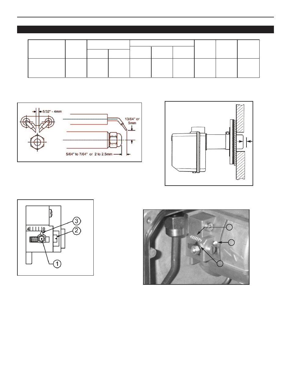
Model BF-5 Electrode Setting
Turbulator location
Picture 1
Turbulator Setting
Figure 8
Proper Insertion into Combustion Chamber
TURBULATOR SETTING
1. Loosen nut, 1, then turn the screw, 2, until the index marker, 3, is aligned with the correct index number.
2. Retighten the retaining nut, 1.
The numbers on the casting are there to denote the high and low end of the scale – For Model BF-5, zero and four are
scale indicators only. From left to right, the first line is 4 and the last line is 0.
The air/oil ratio depends on accurate setting of the turbulator disc and air damper.
Be careful when making this adjustment as an incorrect setting will result in an unsatisfactory operation.
See figure 8 & 9.
Figure 7
Figure 9
3
2
1
1/4”
RIELLO BURNER DATA – BURNER MODEL BF-5