Slant/Fin Gas Conversion Field User Manual
Page 20
GAS RATE TABLE
Cubic Feet
Boiler rated input
Gas Consumption
cu. ft./hr. of 1000 Btu/cu. ft.
1000 Btu/cu.ft. gas, in 3
Natural Gas
minutes, at rated input
33
1.65
34
1.70
60
3.00
70
3.50
75
3.75
90
4.50
100
5.00
105
5.25
120
6.00
125
6.25
140
7.00
150
7.50
175
8.75
180
9.00
200
10.00
210
10.50
225
11.25
245
12.25
250
12.50
275
13.75
300
15.00
325
16.25
350
17.50
375
18.75
399
19.95
The gas metered in 3 minutes to obtain rated input for each boiler
model using 1000 Btu/cu.ft. gas is tabulated in the gas rate table.
B. Main Burner
1. Fire the boiler continuously for at least 15 minutes,
to reach burner operating temperature.
2. Observe the flames, all burners. The base of all
flame jets should be blue. The tips should be blue
shading to orange.
NOTE: Dust, disturbed by any movement, will
cause bright orange flames. Wait for dust to settle.
3. For one burner, close the air shutter until some of
its flame jet tips turn yellow-white, indicating insuf-
ficient primary air. Then open shutter until whitish
tips disappear completely. Set all burner shutters
to the same opening. Observe to make sure that
no yellow-white tips appear over any portion of
the flame. Small yellow tips at the pilot location are
permitted.
NOTE: This adjustment method gives MINIMUM
primary air setting for safe combustion. DO NOT
attempt to make this adjustment unless burners
are at operating temperature. Adjustment should
be made with burner access panel in final operat-
ing position. Use of a mirror may be helpful to
observe flames. Note that burner ports are on top
of main burner tube.
C.Main Burner Ignition Checkout and Pilot Adjustment
1. The pilot flame must not smother or snuff out
when tested as follows:
a. Main burner ignition from cold start-repeat.
b. Continued operation of main burner.
c. Main burner ignition with appliance at maxi
mum operating temperature after prolonged
operation.
NOTE: Observe operation of the pilot burner with
appliance doors in the final operating position.
Use of a mirror may be helpful.
2. Safety Shutdown Checkout
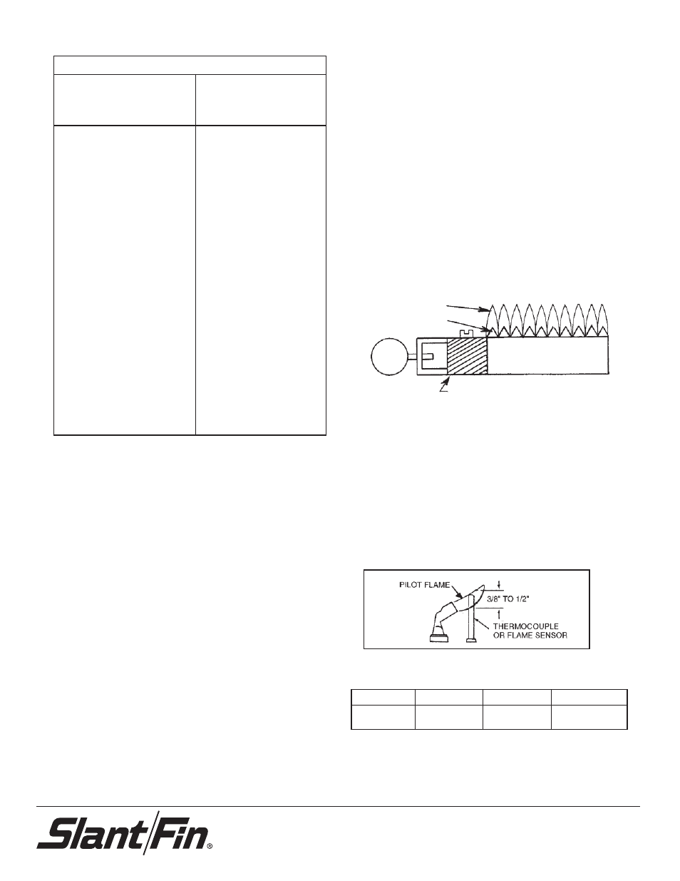
a. For proper operation the pilot should engulf the
thermocouple or flame sensor as shown below.
b. To adjust pilot, turn pilot flow adjustment screw
on valve clockwise or counterclockwise to give
a steady flame enveloping 3/8" to 1/2" inch of
the tip of the thermocouple or flame sensor.
Note that turning the pilot adjustment screw
clockwise will decrease the pilot flame.
SLANT/FIN CORPORATION, Greenvale, N.Y. 11548 • Phone: (516) 484-2600
FAX: (516) 484-5921 • Canada: Slant/Fin
LTD/LTEE
, Mississauga, Ontario
www.slantfin.com
Main Burner
Flame Tips
Blue Flame Base
Front-back sliding primary air
shutter locking screw on top.
Manifold
Gas
Manifold
Minimum Inlet
Maximum Inlet
Natural Gas
3.5”
5”
11”
LP Propane
9.5”
11”
14”
Gas Pressure (inches of wc)