Slant/Fin LX-150CB User Manual
Page 26
Lynx Combi Boiler
26
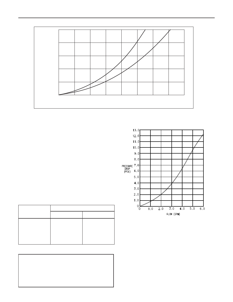
Figure 19. Boiler water side pressure drop
Table 2. DHW teperature rise vs. water flow
0
0
2
4
6
8
10
12
14
2
4
6
8
10
Head
(feet w.c.)
Flow Rate (GPM)
15
LX
-1
50CB
LX
-1
20CB
DOMESTIC HOT WATER
Lynx combi boilers are designed to provide virtually instant
domestic hot water for domestic purposes.
The combi boilers are set for DHW priority. The DHW circulator
is sized to provide adequate hot water production. A flow
switch is provided to detect domestic water flow and to ener-
gize the DHW circulator. It also gives a call for the burner to
operate as required for the demand. Minimum flow rate
required to activate DHW system is 0.3 GPM.
Hot water temperature to the fixtures depends to the following
parameter:
a. Temperature of the incoming cold water
b. Tempering valve setting
c. Total water flow rate (see table 2)
d. Boiler supply water temperature to domestic hot water
production system (“d”), “d” value is settable from
104˚F to 185˚F (see table 4)
Temperature
Rise, ˚F
DHW Flow Rate, GPM
LX-120CB
LX-150CB
100
80
70
60
55
2.0
2.5
3.0
3.5
4.0
2.3
3.3
4.0
4.5
5.0
WARNING - HOT WATER CAN SCALD!
A tempering valve must be installed on the hot water outlet
to all fixtures where direct user contact can be made with the
water supplied by the DHW system, to prevent any possible
scalding conditions. See Figure 23 for the appropriate instal-
lation method of this device (not supplied with the boiler).
DHW PIPING
1. Make all piping connections to and from DHW system of
the combi boiler as shown in figure 23.
2. Isolation valves and unions are recommended on piping
connections to facilitate any possible service need. Use
full port valves to ensure proper water flow through the
DHW system.
3. Piping for each domestic water should be adequately
sized for the desired flow rates and each fixture. The
distance to each fixture should be considered for the
response rate of adaquate hot water to each of them.
CAUTION: A tempering valve (not supplied with boiler) is
recommended to be installed on the hot water outlet to all
fixtures where direct user contact can be made with the hot
water supplied by the DHW system to prevent any possible
scalding conditions. See figure 23.
DHW Pressure drop vs. flow