Slant/Fin Jaguar User Manual
Page 20
Jaguar Caravan Multiple and Cascading Boilers
20
Maximum of 8 boilers could be set up for cascading. See page 3 for
piping instruction. A water supply system sensor (12 k ohm thermistor)
is required to operate and control the system. Slant/Fin system sensor
part number is 833433000.
One boiler of the system would be designated as the Master boiler
(boiler #1) and all other boilers would be designated as Follower boilers
(boiler #2 to 8). Once there is a call for heat, the Master control will turn
on the fewest boilers possible to meet the load. The control will bring on
and modulate the first boiler from its minimum capacity to its maximum
capacity before bringing on another boiler. When another boiler is
turned on, the previous boiler will be kept on its maximum rate.
10.1 ELECTRICAL WIRING
Schematic and ladder wiring diagrams are shown on figure 7a
and 7b.
Field wiring connections for Jaguar link cascading method must be
as follows:
9.1.1
Power supply: A separately fused circuit is required for each
boiler. Use standard 15 Amp. fuse or breaker and 14 gauge
conductors in BX cable or conduit. Provide disconnect
means and overload protection as required. Boilers must be
electrically grounded in accordance with the requirements of
the authority having jurisdiction, or, in the absence of such
requirements, with the National Electrical Code, ANSI/NFPA
70- latest edition.
Connect power supply to terminal #21 (hot) and #22
(neutral). Connect the ground wire to the green ground
screw next to the terminal strip.
Proper polarity is critical for the power supply connections. Reversed
polarity will cause boiler lockout. Proper grounding is critical for
boiler operation.
10.1.2 Boiler circulator: Connect boiler circulator to terminal
#19 and 20 if the system is for space heating only.
10.1.3 System circulator: System circulator must be powered
externally and may require the use of relay and a separate
power source.
10.1.4 Space heating thermostat(s): Install thermostat on an inside
wall and away from any heat sources, sunshine and drafts.
Connect room thermostat (if used) to terminal #1 and 2 of
Master boiler. Use low voltage style thermostats, relays or
zone valve end switches (isolated contacts).
10.1.5 System water supply sensor: A system sensor (12 K ohm
thermistor) is required for the system. Slant/Fin part number
is 833433000. Connect sensor wires to terminal #5 and 6 of
Master boiler. Follow instruction provided with the sensor for
installation.
10.1.6 Outdoor air sensor: The outdoor sensor is 12k ohm
thermistor supplied with the boiler. Mount the sensor on
an outside wall shielded from direct sunlight or flow of heat
or cooling from other sources. See instructions provided with
the sensor. Connect sensor wires to terminal #5 and 6 of
boiler #2.
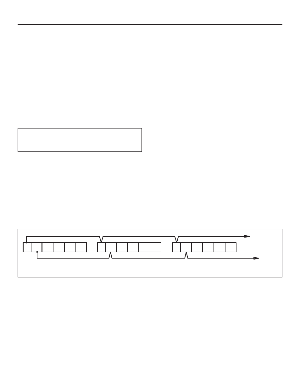
10.1.7 Jaguar link connections: Connect terminal #9 and 10 of
Master boiler to terminal #9 and 10 of all individual
Follower boilers. See figure 13.
DANGER:
Before wiring always turn off electric power
supply. Otherwise shock or death can result.
10. CONTROL USING BUILT-IN JAGUAR LINK CASCADING METHOD
9 10 11 12 13 14
9 10 11 12 13 14
9 10 11 12 13 14
Master boiler (boiler #1)
field wiring terminal strip
Follower boiler (boiler #2)
field wiring terminal strip
Follower boiler (boiler #3)
field wiring terminal strip
To next
boiler
To next
boiler
Figure 13. Jaguar link connections.