SilentKnight SK-Mon-10 Addressable Ten Input Monitor Module User Manual
Page 3
SK-460-009
3
I56-3443-000
©2009 Silent Knight
FCC STATEMENT
This device complies with part 15 of the FCC Rules. Operation is subject to the following two conditions: (1) This device may not cause harmful interference, and (2) this device must
accept any interference received, including interference that may cause undesired operation.
NOTE: This equipment has been tested and found to comply with the limits for a Class B digital device, pursuant to Part 15 of the FCC Rules. These limits are designed to provide
reasonable protection against harmful interference in a residential installation. This equipment generates, uses and can radiate radio frequency energy and, if not installed and used
in accordance with the instructions, may cause harmful interference to radio communications. However, there is no guarantee that interference will not occur in a particular installa-
tion. If this equipment does cause harmful interference to radio or television reception, which can be determined by turning the equipment off and on, the user is encouraged to try
to correct the interference by one or more of the following measures:
– Reorient or relocate the receiving antenna.
– Increase the separation between the equipment and receiver.
– Connect the equipment into an outlet on a circuit different from that to which the receiver is connected.
– Consult the dealer or an experienced radio/TV technician for help.
0
1
2
3
4
5 6
7 8 9
BASE ADDRESS
TO NEXT
DEVICE
–
STATUS
INDICATORS
—
+
—
+
—
+
—
+
—
+
—
+
IDC
ADDRESS
+0
+1
+2
+3
+4
+5
+6
+7
+8
+9
IDC
ADDRESS
IDC
ADDRESS
IDC
ADDRESS
IDC
ADDRESS
—
+
—
+
SLC
—
+
—
+
+
–
+
FROM PANEL OR
PREVIOUS DEVICE
47K
EOL
RESISTOR
ELR-47K
CONNECT MODULES TO
LISTED COMPATIBLE
SILENT KNIGHT CONTROL
PANELS ONLY
SIGNAL LINE CIRCUIT (SLC) 32 VDC MAX.
SEE PANEL INSTRUCTION MANUAL
FOR WIRE REQUIREMENTS.
CLASS B IDC (TYPICAL)
—
+
—
+
A/B SLCT
COM LOSS
DISABLE 1
DISABLE 2
0
1
2
3
4
5 6
7 8 9
10
11
12
13
14
15
POWER LIMITED
AND SUPERVISED
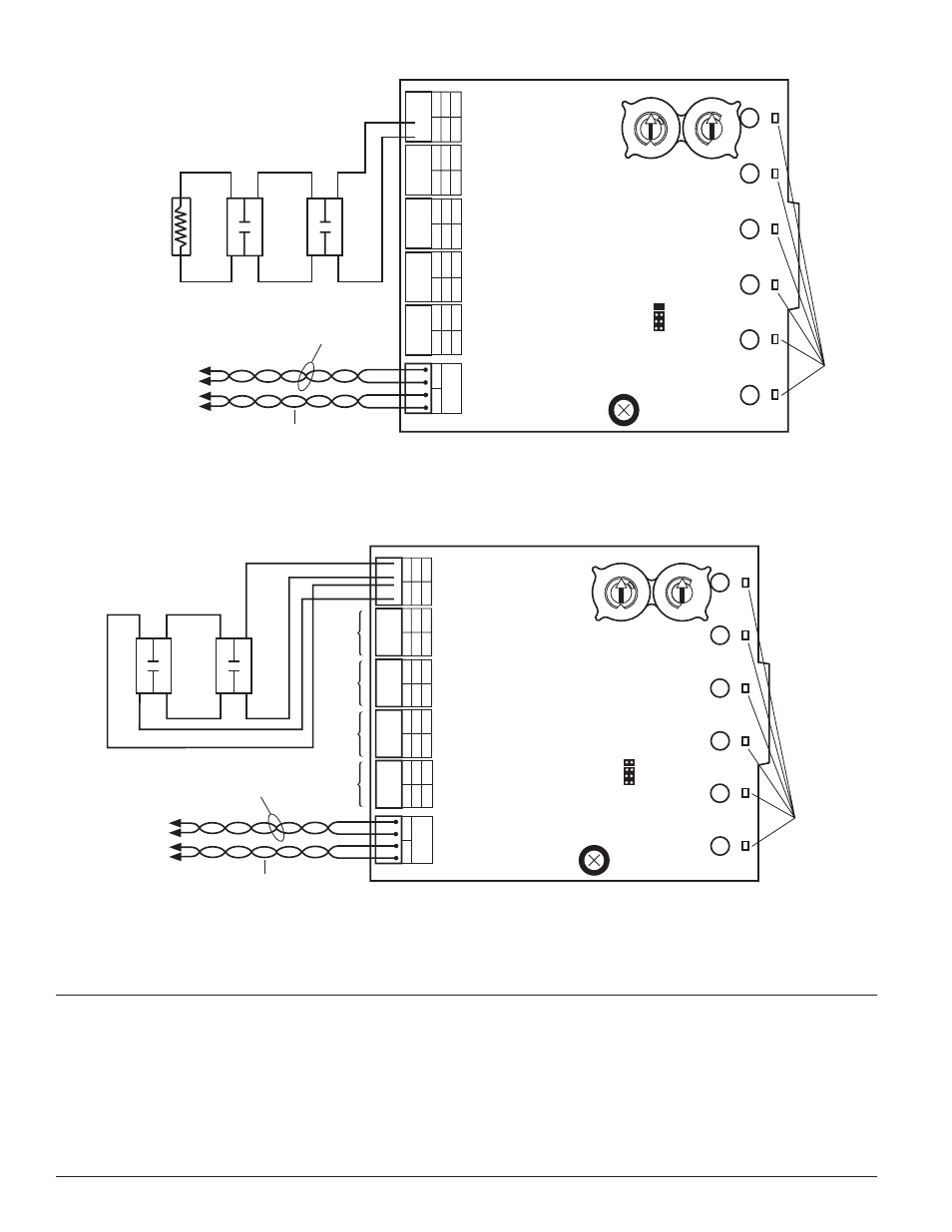
NOTE:
Any number of UL listed contact closure devices may be used. DO
NOT mix fire alarm initiating and supervisory devices on the same initiating
device circuit. Install contact closure devices per manufacturer’s installation
instructions.
C0810-02
FIGURE 5: TYPICAL INITIATING DEvICE CIRCUIT CONFIGURATION – CLASS B, STYLE B.
BASE ADDRESS
TO NEXT
DEVICE
–
STATUS
INDICATORS
—
+
—
+
—
+
—
+
—
+
—
+
IDC
ADDRESS
+0
+1
+2
+3
+4
+5
+6
+7
+8
+9
IDC
ADDRESS
IDC
ADDRESS
IDC
ADDRESS
IDC
ADDRESS
—
+
—
+
SLC
—
+
—
+
+
–
+
FROM PANEL OR
PREVIOUS DEVICE
CONNECT MODULES TO
LISTED COMPATIBLE
SILENT KNIGHT CONTROL
PANELS ONLY
SIGNAL LINE CIRCUIT (SLC) 32 VDC MAX.
SEE PANEL INSTRUCTION MANUAL
FOR WIRE REQUIREMENTS.
CLASS A IDC (TYPICAL)
—
+
—
+
A/B SLCT
COM LOSS
DISABLE 1
DISABLE 2
IDC 2
IDC 3
IDC 4
IDC 5
0
1
2
3
4
5 6
7 8 9
0
1
2
3
4
5 6
7 8 9
10
11
12
13
14
15
POWER LIMITED
AND SUPERVISED
REMOVE SHUNT FOR CLASS A.
FIGURE 6: TYPICAL FAULT TOLERANT INITIATING DEvICE CIRCUIT CONFIGURATION – CLASS A, STYLE D
NOTE:
Any number of UL listed contact closure devices may be
used. DO NOT mix fire alarm initiating and supervisory devices on the
same initiating device circuit. Install contact closure devices per manu-
facturer’s installation instructions.
C0811-02