Class a (style d) wiring, Auxiliary power using flexput™ circuits, For more information – SilentKnight SD500-SDM Smoke Detector Module User Manual
Page 2: Two-wire smoke detectors
SD500-SDM Installation Instructions
2
P/N 151193
(Style B) supervision position (see Figure 4).
Figure 2: Class B (Style B) 2-Wire Detector Loop
Note: Auxiliary power is supplied by a Regulated UL listed
power supply for Fire Protective Signalling Systems.
Class A (Style D) Wiring
Wire Class A (Style D) conventional smoke
detector loop to the SD500-SDM as shown in
Figure 3. Place the jumper block in the Class A
(Style D) supervision position (see Figure 4).
Figure 3: Class A (Style D) 2-Wire Detector Loop
Figure 4: Supervision Selection Jumper
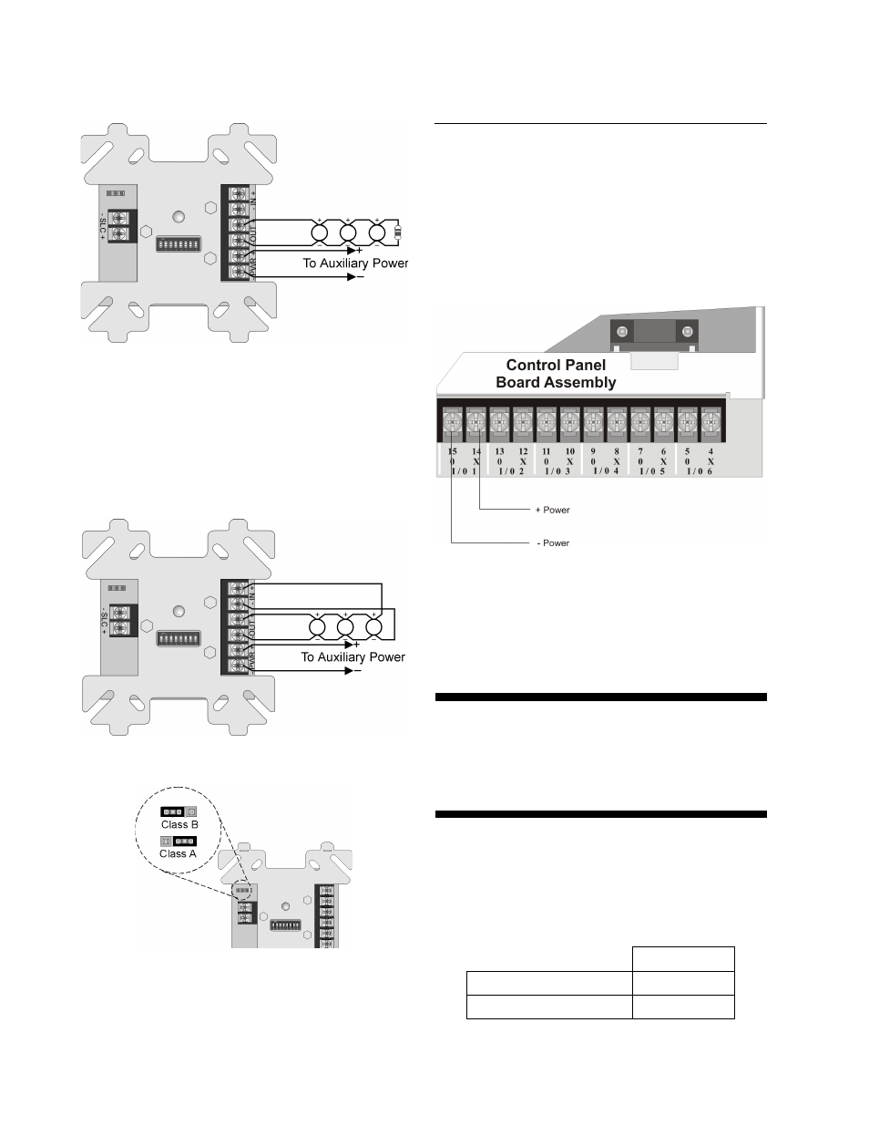
Auxiliary Power Using
Flexput™ Circuits
The SD500-SDM can use aux power from any
24 VDC source. The following describes how to
use the Flexput circuits as the auxiliary power
source:
1. Connect the aux power wires to the Flexput
terminals using “X” terminals as positive
and “O” terminals as negative power. See
Figure 5.
Figure 5: Flexput Auxiliary Power Output
2. Configure the auxiliary power output for
constant output through programming. Refer
to the FACP installation manual form more
information.
For More Information
This document is for quick reference. For more
information, refer to the FACP installation
manual.
Two-Wire Smoke Detectors
Table 1 lists two-wire smoke detectors that are
compatible with the fire control panel. The table
is organized by manufacturer. The columns
show the number of detectors per loop that can
be used.
SD500-SDM
Identifier
24H
Operating Voltage Range
18.5–27.4 VDC