Tens ones – SilentKnight HFS-T User Manual
Page 2
HW-400-006
2
I56-3485-000R
Make electrical connections by stripping about 3/8 inch (10 mm) of insulation
from the end of the wire (use strip gauge molded in base), sliding the bare end
of the wire under the clamping plate, and tightening the clamping plate screw.
Do not loop the wire under the clamping plate.
The zone wiring of the detector base should be checked before the detector
heads are installed in them. The wiring should be checked for continuity and
polarity in the base, and dielectric tests should be performed.
The base includes a label for recording the zone, address, and type of detector
being installed. This information is important to set the address of the detector
head that will later be plugged into the base and to verify the type required
for that location.
Remove power from the communication line before installing sensors.
1. Wire the sensor base per the wiring diagram, Figure 3.
2. Reference the control panel device address map to determine appropriate
addressing.
3. Set the desired address on the sensor address switches, see Figure 4.
4. Install the sensor into the sensor base. Push the sensor into the base
while turning it clockwise to secure it in place.
5. After all sensors have been installed, apply power to the control unit and
activate the communication line.
6. Test the sensor(s) as described in the TESTING section of this manual.
CAUTION
Dust covers provide limited protection against airborne dust particles during
shipping. Dust covers must be removed before the sensors can sense smoke.
Remove sensors prior to heavy remodeling or construction. Figure 3. WIRING
DIAGRAM:
+
–
–
+
UL
LISTED COM
P
A
TIBLE
CONTROL
P
ANEL
CAUTION: DO NOT LOOP WIRE
UNDER TERMINAL 1 OR 2.
BREAK WIRE RUN TO PROVIDE
SUPERVISION OF CONNECTIONS.
OPTIONAL RETURN LOOP
C1010-02
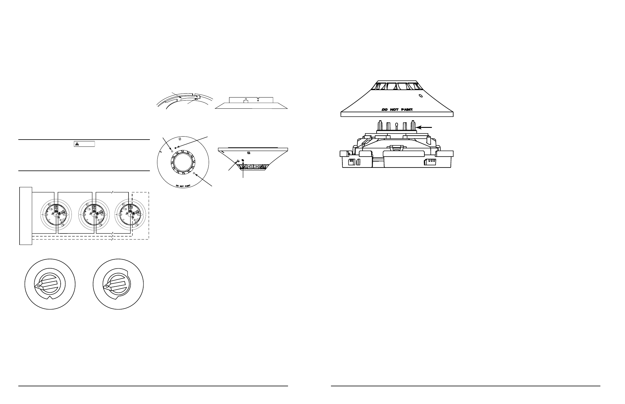
FIGURE 4. ROTARy ADDRESS SWITCHES:
TENS
ONES
9
10
11
12
13
14
15
8
7
6
5
4
3
2
1 0
9
8
7
6
5
4
3
2
1 0
C0162-00
TAMPER RESISTANCE
The Tamper Resistant Tab, in the Detector Mounting Base, can make the de-
tector tamper-resistant by making it necessary to use a small screwdriver or
similar tool to detach the detector from the base.
To make the detector tamper-resistant, use needle-nose pliers to break the
smaller tab at the scribed line on the tamper resistant tab. Figures 5 and 6
show the location of this tab on the detector mounting bracket.
To remove the detector from the base after it has been made tamper resistant,
insert a small screwdriver into the notch, as indicated in Figure 1, and press
the plastic lever toward the mounting surface before rotating the detector
counterclockwise for removal.
C0196-01
LED
LED
MAGNET
TEST MARKER
LED
MAGNET
TEST MARKER
FIGURE 6. VIEWS SHOWING POSITION OF TEST MAGNET:
PLASTIC LEVER
BREAK TAB AT DOTTED LINE BY
TWISTING TOWARD CENTER OF BASE
USE SMALL-BLADED SCREWDRIVER TO PUSH
PLASTIC LEVER IN DIRECTION OF ARROW
FIGURE 5: ENABLING THE TAMPER-RESISTANT CAPABILITy
C0130-00
TESTING
Before testing, notify the proper authorities that the system is undergoing
maintenance, and will temporarily be out of service. Disable the system to
prevent unwanted alarms.
All sensors must be tested after installation and periodically thereafter. Test-
ing methods must satisfy the Authority Having Jurisdiction (AHJ). Sensors
offer maximum performance when tested and maintained in compliance with
NFPA 72.
A. Test Magnet (Model No. M02-04 – optional)
1. Place the optional test magnet against the cover in the magnet test
area, as shown in Figure 6, to activate the test feature.
2. The LEDs should latch on within 10 seconds, indicating alarm and
annunciating the panel.
3. Reset the detector at the system control panel.
B. Direct Heat Method (Hair dryer of 1000 – 1500 watts)
1. From the side of the detector, direct the heat toward the sensor. Hold
the heat source about 6 inches (15 cm) away to prevent damage to
the cover during testing.
2. The LEDs on the detector should light when the temperature at the
detector reaches the alarm setpoint. If the LEDs fail to light, check the
power to the detector and the wiring in the detector base.
3. Reset the detector at the system control panel.
A sensor that fails any of these tests should be cleaned as described under
CLEANING, and retested. If the sensor fails after cleaning, it must be replaced
and returned for repair.
When testing is complete, restore the system to normal operation and notify
the proper authorities that the system is back in operation.
HW-400-006
3
I56-3485-000R
SENSING
CHAMBER
C0197-01
FIGURE 7:
MAINTENANCE: (SEE FIGURE 7)
NOTE: Before cleaning notify the proper authorities that the system is un-
dergoing maintenance, and therefore the system will temporarily be out of
service. Disable the loop or system undergoing maintenance to prevent un-
wanted alarms.
It is recommended that the sensor be removed from its mounting base for
easier cleaning and that sensors be cleaned at least once a year. Use a vacuum
cleaner to remove dust from the sensing chamber.
SPECIAL NOTE REGARDING SMOKE DETECTOR GUARDS
Smoke detectors are not to be used with detector guards unless the combina-
tion has been evaluated and found suitable for that purpose.