Tens ones – SilentKnight HFS-PT User Manual
Page 2
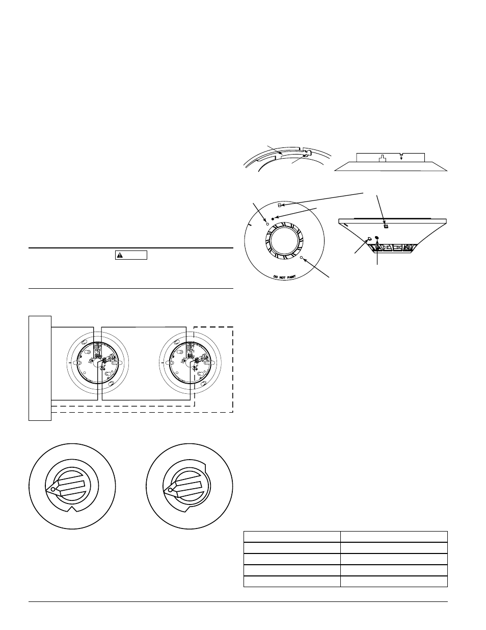
LED
LED
MAGNET
TEST MARKER
TAMPER-RESISTANT SLOT
LED
MAGNET
TEST MARKER
HW-400-005
2
I56-3483-000R
If shielded cable is used, the shield connection to and from the detector must
be continuous by using wire nuts, crimping, or soldering, as appropriate for a
reliable connection.
Make electrical connections by stripping about
3
/
8
inch (10 mm) of insulation
from the end of the wire (use strip gauge molded in base), sliding the bare end
of the wire under the clamping plate, and tightening the clamping plate screw.
Do not loop the wire under the clamping plate.
The zone wiring of the detector base should be checked before the detector
heads are installed in them. The wiring should be checked for continuity and
polarity in the base, and dielectric tests should be performed.
The base includes a label for recording the zone, address, and type of detector
being installed. This information is important to set the address of the detector
head that will later be plugged into the base and to verify the type required
for that location.
Remove power from the communication line before installing sensors.
1. Wire the sensor base per the wiring diagram, Figure 3.
2. Reference the control panel device address map to determine appropriate
addressing.
3. Set the desired address on the sensor address switches, see Figure 4.
4. Install the sensor into the sensor base. Push the sensor into the base
while turning it clockwise to secure it in place.
5. After all sensors have been installed, apply power to the control unit and
activate the communication line.
6. Test the sensor(s) as described in the TESTING section of this manual.
CAUTION
Dust covers provide limited protection against airborne dust particles during ship-
ping. Dust covers must be removed before the sensors can sense smoke. Remove
sensors prior to heavy remodeling or construction.
tamPeR-ReSIStanCe
The Tamper Resistant Tab, in the Detector Mounting Base, can make the de-
tector tamper-resistant by making it necessary to use a small screwdriver or
similar tool to detach the detector from the base.
To make the detector tamper-resistant, use needle-nose pliers to break the
smaller tab at the scribed line on the tamper resistant tab. Figures 5 and 6
show the location of this tab on the detector mounting bracket.
To remove the detector from the base after it has been made tamper resistant,
insert a small screwdriver into the notch, as indicated in Figure 1, and press
the plastic lever toward the mounting surface before rotating the detector
counterclockwise for removal.
FIGURe 4. ROtaRy aDDReSS SWItCHeS:
FIGURe 3. WIRInG DIaGRam:
TENS
ONES
9
10
11
12
13
14
15
8
7
6
5
4
3
2
1 0
9
8
7
6
5
4
3
2
1 0
C0162-00
+
–
–
+
CAUTION: DO NOT LOOP WIRE
UNDER TERMINAL 1 OR 2.
BREAK WIRE RUN TO PROVIDE
SUPERVISION OF CONNECTIONS.
UL
LISTED COM
P
A
TIBLE
CONTROL
P
ANEL
OPTIONAL RETURN LOOP
C0100-03
PLASTIC LEVER
BREAK TAB AT DOTTED LINE BY
TWISTING TOWARD CENTER OF BASE
USE SMALL-BLADED SCREWDRIVER TO PUSH
PLASTIC LEVER IN DIRECTION OF ARROW
FIGURe 5: enaBLInG tHe tamPeR-ReSIStant CaPaBILIty
CO130-00
teStInG
Before testing, notify the proper authorities that the system is undergoing
maintenance, and will temporarily be out of service. Disable the system to
prevent unwanted alarms.
All sensors must be tested after installation and periodically thereafter. Test-
ing methods must satisfy the Authority Having Jurisdiction (AHJ). Sensors
offer maximum performance when tested and maintained in compliance with
NFPA 72.
The sensor can be tested in the following ways:
A. Functional: Magnet Test (P/N M02-04-01 or M02-09-00)
This sensor can be functionally tested with a test magnet. The test mag-
net electronically simulates smoke in the sensing chamber, testing the
sensor electronics and connections to the control panel.
1. Hold the test magnet in the magnet test area as shown in Figure 6.
2. The sensor should alarm the panel.
Two LEDs on the sensor are controlled by the panel to indicate sensor
status. Coded signals, transmitted from the panel, can cause the LEDs
to blink, latch on, or latch off. Refer to the control panel technical docu-
mentation for sensor LED status operation and expected delay to alarm.
B. Smoke Entry
The GEMINI model 501 aerosol generator can be used for smoke entry
testing. Set the generator to represent 4%/ft to 5%/ft obscuration as de-
scribed in the GEMINI 501 manual. Using the bowl shaped applicator,
apply aerosol until the panel alarms.
Additionally, canned aerosol simulated smoke (canned smoke agent)
may be used for smoke entry testing of the smoke detector. Tested and
approved aerosol smoke products are:
manUFaCtUReR
mODeL
Home Safeguard Industries
25S
SDi
CHEK02 and CHEK06
SDi
SOLOA4
SDi
SMOKESABRE-01
FIGURe 6:
C0196-02