Ra + ra, Remote alarm led option 1 per unit – SilentKnight HFS-D User Manual
Page 4
[7.1]wIRINg INSTRUCTIONS
Disconnect power from the communication line before installing the HFS-D
duct smoke detector.
The HFS-D detectors are designed for easy wiring. The housing provides a ter-
minal strip with clamping plates. Wiring connections are made by sliding the
bare end under the plate, and tightening the clamping plate screw. See Figure
6 below for system wiring.
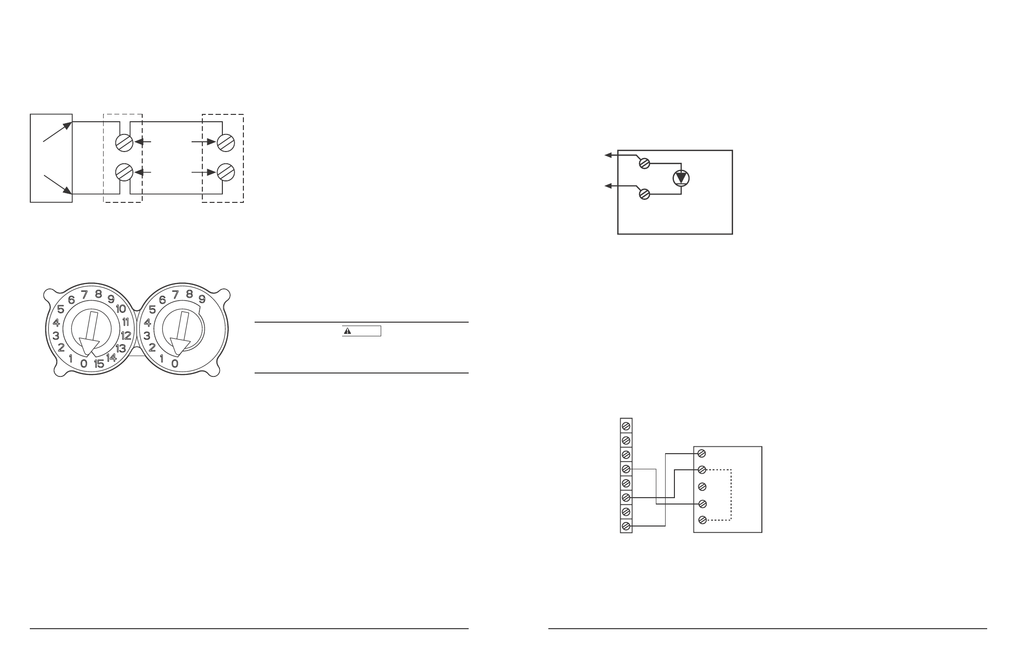
[7.2] SET THE ADDRESS
Set the desired address on the sensor head code wheel switches. on the back
of the sensor head.
FIgURE 7. ROTARy ADDRESS SwITCHES
[8] VERIFICATION OF OPERATION
[8.1]INSTALL THE COVER
Install the covers making sure that the cover fits into the base groove. Tighten
the seven screws that are captured in the covers. Note that the cover must be
properly installed for proper operation of the sensor.
NOTE: Verify sensor cover gasket is properly seated on cover prior to cover
installation.
[8.2] POwER THE UNIT
Activate the communication line on terminals COM + and COM –.
[8.3] DETECTOR CHECk
Standby – If programmed by the system control panel, look for the presence of
the flashing LEDs through the transparent housing cover. The LED will flash
with each communication.
Trouble – If programmed by the system control panel and the detector LEDs
do not flash, then the detector lacks power (check wiring, missing or improp-
erly placed cover, panel programming, or power supply), the sensor head is
missing (replace), or the unit is defective (return for repair).
[8.4]DUCT SMOkE DETECTOR TEST & MAINTENANCE PROCEDURES
Test and maintain duct smoke detectors as recommended in NFPA 72. The
tests contained in this manual were devised to assist maintenance personnel
in verification of proper detector operation.
Before conducting these tests, notify the proper authorities that the smoke
detection system will be temporarily out of service. Disable the zone or system
under test to prevent unwanted alarms.
[8.4.1]TEST THE UNIT
1. M02-04-00 Magnet Test – This sensor can be functionally tested with a
test magnet. The test magnet electronically simulates smoke in the sensing
chamber, testing the sensor electronics and connections to the control panel.
2. Remote Test Accessory – The use of a remote accessory for visible indica-
tion of power and alarm is recommended.
Verify system control panel alarm status and control panel execution of all
intended auxiliary functions (i.e. fan shutdown, damper control, etc.).
Two LEDs on the sensor are controlled by the panel to indicate sensor sta-
tus. Coded signals, transmitted from the panel, can cause the LEDs to blink,
latch on, or latch off. Refer to the control panel technical documentation for
sensor LED operation and expected delay to alarm.
[8.4.2] THE DETECTOR MUST BE RESET By THE SySTEM CONTROL PANEL
[8.4.3]SMOkE ENTRy TEST USINg AEROSOL SMOkE
This test is intended for low-flow systems (100-500 FPM). If the air speed is
greater than 500 FPM, use a conventional manometer to measure differential
pressure between the sampling tubes, as described under Measurement Tests
on Page 3.
Drill a
1
⁄
4
-inch hole 3 feet upstream from the duct smoke detector. With the air
handler on, measure the air velocity with an anemometer. Air speed must be
at least 100 FPM. Spray aerosol smoke* into the duct through the
1
⁄
4
-inch hole
for five seconds. Wait two minutes for the duct smoke detector to alarm. If the
duct smoke detector alarms, air is flowing through the detector. Remove the
duct smoke detector cover and blow out the residual aerosol smoke from the
chamber and reset the duct smoke detector at the panel. Use duct tape to seal
the aerosol smoke entry hole. Remember to replace the cover after the test or
the detector will not function properly.
*Aerosol smoke can be purchased from Home Safeguard Industries at home-
safeguard.com, model 25S Smoke Detector Tester, and Chekkit Smoke Detector
Tester model CHEK02 and CHEK06 available from SDi. When used properly,
the canned smoke agent will cause the smoke detector to go into alarm. Re-
fer to the manufacturer’s published instructions for proper use of the canned
smoke agent.
CAUTION
Canned aerosol simulated smoke (canned smoke agent) formulas will vary by
manufacturer. Misuse or overuse to these products may have long term adverse
effects on the smoke detector. Consult the canned smoke agent manufacturer’s
published instructions for any further warnings or caution statements.
[9]DETECTOR CLEANINg PROCEDURES
Notify the proper authorities that the smoke detector system is undergoing
maintenance, and that the system will temporarily be out of service. Disable
the zone or system undergoing maintenance to prevent unwanted alarms and
possible dispatch of the fire department.
[9.1]DETECTOR SENSOR
1. Remove the sensor to be cleaned from the system.
2. Remove the sensor cover by pressing firmly on each of the four removal
tabs that hold the cover in place.
3. Vacuum the screen carefully without removing it. If further cleaning is re-
quired continue with Step 4, otherwise skip to Step 7.
4. Remove the chamber cover/screen assembly by pulling it straight out.
5. Use a vacuum cleaner or compressed air to remove dust and debris from
the sensing chamber.
6. Reinstall the chamber cover/screen assembly by sliding the edge over the
sensing chamber. Turn until it is firmly in place.
7. Replace the cover using the LEDs to align the cover and then gently pushing
it until it locks into place.
8. Reinstall the detector.
[9.2]REINSTALLATION
1. Reinstall the detector in its housing.
2. Restore system power.
3. Perform Detector Check.
4. Notify the proper authorities testing has been completed and the smoke
detector system is back in operation.
FIgURE 6. SySTEM wIRINg DIAgRAM FOR HFS-D:
HO572-00
COMM.
LINE (+)
UL/FM LISTED
CONTROL
PANEL
1ST
DETECTOR
IN LOOP
2ND
DETECTOR
IN LOOP
COMM.
LINE (–)
COMM.
LINE
HO112-00
HW-300-000
4
I56-3488-001R
HW-300-000
5
I56-3488-001R
[10]SENSOR REPLACEMENT
1. Remove the sensor head by rotating counterclockwise.
2. Pull gently to remove it.
3. To replace the sensor head, align the mounting features and rotate clock-
wise into place.
[11] OPTIONAL ACCESSORIES
Optional accessories include RA400Z/RA100Z, RTS451/RTS151 and
RTS451KEY/RTS151KEY.
NOTE: Ensure blue wire always remains connected to RA+ on the field
connector side of the terminal block.
Note: If using a RA400Z, the tab should be broken for use with the intelli-
gent duct smoke detector. If using RA100Z, ensure that jumper is removed.
[11.1] REMOTE TEST USINg HFS-DPR, SENSOR wITH
REMOTE TEST CAPABILITy:
The RTS451/RTS151/RTS451KEY/RTS151KEY Remote Test Station facilitates
test of the alarm capability of the duct smoke detector. These accessories
provide the stimulus to initiate an alarm condition at the detector. The HFS-D
duct smoke detector must be reset by the system control panel.
To install the RTS451/RTS151/RTS451KEY/RTS151KEY, using the HFS-DPR,
sensor with remote test capability, connect the device as shown in Figure 9;
wire runs must be limited to 25 ohms or less per interconnecting wire.
NOTE: Resistor assembly must be in place between RA+ and OUT+
inside the HFS-D for Remote Test function to operate.
RTS451/RTS451KEY
RTS151/RTS151KEY
JUMPER
4
5
3
2
1
TEST COIL +
TEST COIL –
COMM +
OUT (CONV ONLY) +
COMM –
RA/RTS –
RA +
RTS +
H0633-00
FIgURE 9. RTS451/RTS451kEy/RTS151/RTS151kEy USINg
HFS-DPR, SENSOR wITH REMOTE TEST CAPABILITy
FIgURE 8. wIRINg DIAgRAM FOR HFS-D TO RA400Z/RA100Z:
[11.2] ADDITIONAL MODULE OPTION
The HFS-D can also accommodate a relay or control module (sold separately)
within the power board side of the housing. The relay or control module must
be listed as compatible to the fire alarm control panel.
Physical Module Mounting
1) Remove the breakaway tabs at the four corners of the module
2) Locate the module at right most corner of the power board. The upper
left corner mounting hole of the module will align with a screw boss in
the housing.
3) Install a #8×
3
⁄
8
˝ Plastite screw at the screw boss location
Note: See the corresponding module Installation Instructions for general
description, control panel compatibility, wiring and ratings.
(+)
(-)
RA400Z/RA100Z
– RA
+ RA
REMOTE ALARM LED
OPTION 1 PER UNIT
H0570-03