Wiring the led outputs, Dry contact wiring, Setting dip switches – SilentKnight 5880 LED Driver Module User Manual
Page 2
5880 LED I/O Module Installation Instructions
2
© 2008 Honeywell International Inc. PN 150972 Rev C
Wiring the LED Outputs
The 5880 has four 12-pin connectors (P/N
130092) used to connect LEDs. All LED outputs
use a common pin on each connector for LED
power (see Figure 3). Current is limited through
each output so no series resistor is required.
On connector P1, pin 12 is an open collector
output for controlling a piezo (PZT) output. This
output matches the piezo output pattern of the
FACP on-board annunciator.
Note: The open collector PZT output does not have a built-in
current limiting resistor, one is required to limit the max.
sink current (see Specifications for max sink current). The
PZT output is not mappable.
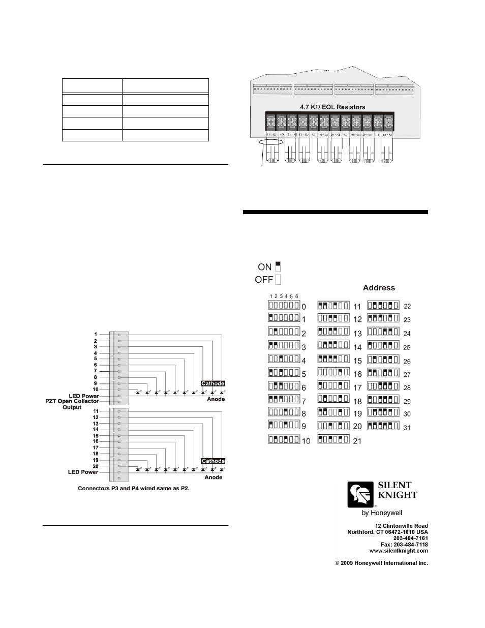
Wire the LED outputs as shown in Figure 3.
Figure 3: 5880 LED Outputs
Dry Contact Wiring
The 5880 has eight input circuits used to monitor
switch inputs such as pull stations, water flow,
tamper, reset, or silence type switches. Wire
contacts as shown in Figure 4.
Figure 4: Dry Contact Wiring
Setting DIP Switches
Each 5880 requires a unique ID number which is
set using the DIP switches on the 5880 circuit
board. See Figure 5 for DIP switch settings.
Figure 5: DIP Switch Settings
Table 2: 5880 to FACP Connections
5880 Terminals
FACP Terminals
B
B
A
A
S+
+
S-
–
P1
P2
All Inputs Supervised/Power Limited