Figure 6 – Sigtronics Dual-CFR User Manual
Page 9
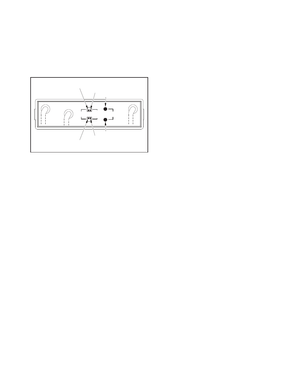
RADIO VOLUME switch for Radio 2
MIC XMIT GAIN RANGE switch for Radio 2
MIC XMIT GAIN ADJ for Radio 2
MIC XMIT GAIN ADJ for Radio 1
MIC XMIT GAIN RANGE switch for Radio 1
RADIO VOLUME switch for Radio 1
RADIO
VOLUME LO
HI
RADIO 2
RADIO 1
HI
LO
MIC
XMIT
RANGE
MIC XMIT
GAIN ADJ
FIGURE 6
to the equipment causing the noise. Contact the company
that makes the offending equipment for a recommendation
on the type of filter to use.
If something does not work as described, go back over the
wiring and correct before going on. If all is well, you can
tighten all headset jacks and secure all jack box covers
with the supplied hardware. Also, tighten and secure all PTT
switches. On the UltraSound unit, turn down the intercom
VOLUME control to approximately the 10 o’clock position.
IV. RADIO HOOK UP
The connection of the UltraSound unit to the vehicle’s radio(s)
should be done by someone familiar with the radio(s) such as
your radio installer. Refer to the UltraSound Wiring Diagram
- Figure 4 on page 5 for CFR units or for Dual-CFR units see
Figure 5 on page 6. Only the radio functions are shown for the
radio end of the UltraSound Radio Interface Cable. Because
the connector(s) used by radio manufacturers varies widely,
you will have to consult the radio manual or manufacturer
for the connector(s) and pin assignments used. Sigtronics
has extensive radio interface experience and can assist with
any question you might have concerning this or any other
aspect of the UltraSound system. See our installation hot line
number located on the last page of this manual.
Note: If installing a Dual-CFR system, connect the radio
Interface Cables (J2) from both CFR units before doing the
adjustments.
First plug J2 of the Radio 1 Interface Cable into P2 of the
Intercom. Then using the radio manuals and the UltraSound
Wiring Diagram, identify the correct signal wires or connec-
tor pins to attach the respective UltraSound wires. For most
radios, these connections are at the back of the radio or radio
control head. For some radios, the only place to connect the
MIC HI and LO and PTT HI and LO wires is to the hand-held
microphone connector.* It is best to wire in such a way that
the radio hand microphone can still be used as normal. Make
sure that you do not physically tie the UltraSound MIC LO and
SPEAKER LO wires to the same pin on the radio, even if they
are tied together inside the radio. As in the headset wiring,
the connections between the UltraSound and radios should
be soldered and insulated for reliability. Do not use crimp
type splices. Use a good quality electrical tape or heat shrink
tubing to cover the soldered connections.
* For the more popular radios of this type Sigtronics manu-
factures plug in “Y” adapters to make these connections easy.
Contact your Sigtronics dealer for pricing and availability.
Note: If installing a Dual-CFR system, after setting the
switches and gain adjustments for the first CFR unit as
instructed below, set the switches and gain on the second
unit to match.
Connect the six wires from the Radio 1 Interface Cable to the
appropriate connections on the vehicle’s radio. Once that is
done you will need to set the RADIO 1 VOLUME switch on
the back of the UltraSound unit. See Figure 6 on page 9. This
switch and the vehicles radio volume control set how loud
you hear the vehicles radio in the headsets. For most applica-
tions the default setting of “LO” (up for Radio 1) is fine. If the
vehicles radio volume has to be turned up too high to hear it
in the headsets, set this switch to the “HI” position (down for
Radio 1). Otherwise leave it in the “LO” position. The switch can
be set with a pen or small flat blade screwdriver.
The last step is to set the Radio 1 Microphone Transmit Gain.
Microphone Transmit Gain (labeled MIC XMIT GAIN) adjust-
ment for the radios is provided on the back of the UltraSound
unit. The adjustment sets the microphone audio level going
to the radios during transmit. The Microphone Transmit Gain
adjustment will need to be initially set to your particular
radios. The gains once set, should never need adjustment
again unless the type of radios used is changed. The follow-
ing simple procedures take you through the adjustment of
the Microphone Transmit Gains.
Radio Microphone Transmit Gain Adjustment can be made
with a small, flat blade screwdriver. Referring to Figure 6, the
gain adjustment is set by two controls - a “HI/LO” RANGE
switch and a rotary “ADJ” control. Set the RADIO 1 MIC XMIT
GAIN RANGE switch to the “LO” position (up for Radio 1). This is
the default factory setting. Adjust the “ADJ” control clockwise
to increase the output gain or level to the radio. Counter-
clockwise rotation decreases it. The basic adjustment concept
is simple. You will be setting the level and clarity of outgoing
radio transmissions through the UltraSound unit headsets, to
match or exceed that of transmissions using the radio’s stan-
dard hand microphone. To do this, you will need to transmit
and receive on the vehicle’s radio to a remote station. Arrange
to have someone nearby with a radio compatible to the radio
you are using with the UltraSound. Then . . .
1. Plug a headset into the Officer’s jack. Make sure that the
volume control on the headset is turned up to full. It is not
necessary to connect the other headsets or Radio 2 for this
adjustment.
2. Put on the Officer’s headset and position the headset
microphone as normal. Turn the UltraSound VOLUME
control all the way down (counter-clockwise). You should
not be able to hear yourself in the headset.
3. With the radio’s hand mic, transmit as normal, to the
remote station. Transmit long enough so that the receiv-
ing station can get “calibrated” to your transmission (voice)
level.
9