B. a – Sigtronics Dual-CFR User Manual
Page 11
b.
a.
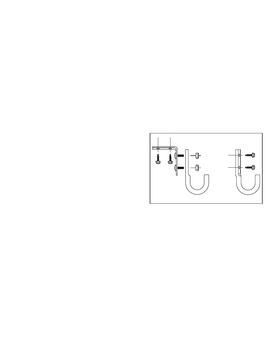
FIGURE 7
nected) on page 8 and fixed any problems there before
you go further. If OK then:
b) Check all six radio interface wires between the
UltraSound unit and the radio — MIC HI, MIC LO, PTT
HI, PTT LO, SPEAKER HI, and LO. Make sure that you have
the correct pin numbers for the radio you are hooking
to. Make sure that MIC LO and SPEAKER LO are not physi-
cally tied to the same pin on the radio; even if they are
tied together inside the radio.
c) If the wiring is OK, then noise is coming from radio:
i) Possible bad radio wiring, (Check radio power and
ground connections for loose or corroded connec-
tions) or. . .
ii) Excessive noise is generated directly by the vehi-
cle’s electrical / charging system - most commonly
known as alternator whine. This is only present when
the vehicle’s engine is running and recognized by the
fact that the pitch or frequency of the whine changes
directly with the change in engine rpm.
The preferred way to solve this type of problem is to
have the vehicle’s electrical / charging system ser-
viced. The most common cause of this type of noise
is bad diodes in the vehicles alternator. Other pos-
sible causes are: Bad vehicle voltage regulator; Bad
alternator or battery cable connections; Missing or
bad engine or alternator grounding straps.
If servicing the vehicle’s charging system is imprac-
tical, installing a good alternator whine power line
filter in-line with the radio power wire(s) will usually
accomplish the same thing. All radio power wires
will have to be filtered. Some radios have more than
one wire that hooks to vehicle power. Contact the
radio manufacturer for a recommendation on the
best filter for the particular radio. NOTE: This solution
should not be considered a permanent fix. Vehicle
charging system problems of this type will eventually
cause other equipment failure as well as shorten the
life of the vehicle’s batteries.
2. Dispatch says too much background noise or unclear or
weak transmissions.
a) Check to see if a radio hand mic on the vehicle is
also active or “live” when transmitting through the
UltraSound unit. Check this while not wearing a head-
set and by talking directly into the radio hand mic and
pressing either UltraSound PTT switches. Do not press
the PTT button on the hand mic itself. If dispatch can
hear you loud and clear, then the background noise
pick up is coming from this active hand mic. If you have
this type of hand mic, then it is best to contact the radio
manufacturer for instructions on a possible microphone
modification to fix the problem. Some radio manufac-
turers can supply a compatible microphone that does
not have this problem.
b) Adjust the UltraSound Radio Mic Transmit Gain con-
trols. If the mic level is set too low, you will get reports
of weak transmissions. If the mic level is too high, you
will get reports of noisy or garbled transmissions. See
“Radio Mic Transmit Gain Adjustment” on page 9.
HEADSET HOOK INSTRUCTIONS
The enclosed headset hooks are provided at no additional
charge to allow for a convenient way to store the headset.
These strong and durable hooks may be mounted in any loca-
tion. Two mounting methods seem to be preferred:
1. Top Mounting ( Figure 7-a ). The hooks may be mounted
from the existing headliner screws and hardware, or you
may use the enclosed attaching screws. When used with
an electric driver these screws are self drilling. For most
metals such as aluminum or common steel, they will not
require a pilot hole. For some stainless steels however,
1⁄8” pilot holes will need to be drilled. Attach the right
angle mounting bracket to the hooks with the machine
screws and lock nuts.
2. Side Mounting ( Figure 7-b ). The hooks may be mounted
on the side of the cab with the enclosed attaching
screws.
Note: The right angle mounting bracket may be shortened
(one hole removed) by cutting with any standard hack saw.
This completes the UltraSound installation.
SYSTEM OPERATION
The following describes how to use the UltraSound System as
well as adjust the UltraSound controls. It also explains exactly
how the UltraSound unit operates. This will allow you to easily
se
t all unit functions to your specific needs. If
you are not familiar
with the UltraSound operation, perform the next few steps
while the vehicle is not in motion.
Headsets
Put on the headset(s) and position the boom mike close to
the mouth, as is the practice with a hand-held mike. For best
voice clarity, the headset microphone must be positioned to
one side of the mouth and 1/4 inch from the lips. Turn the
volume control on the headset ear cup to maximum. Turn
down for individual hearing needs if necessary only after
intercom and radio volumes have been set correctly. (see
next)
11