Ultrasound cfr wiring diagram figure 4 – Sigtronics Dual-CFR User Manual
Page 5
R
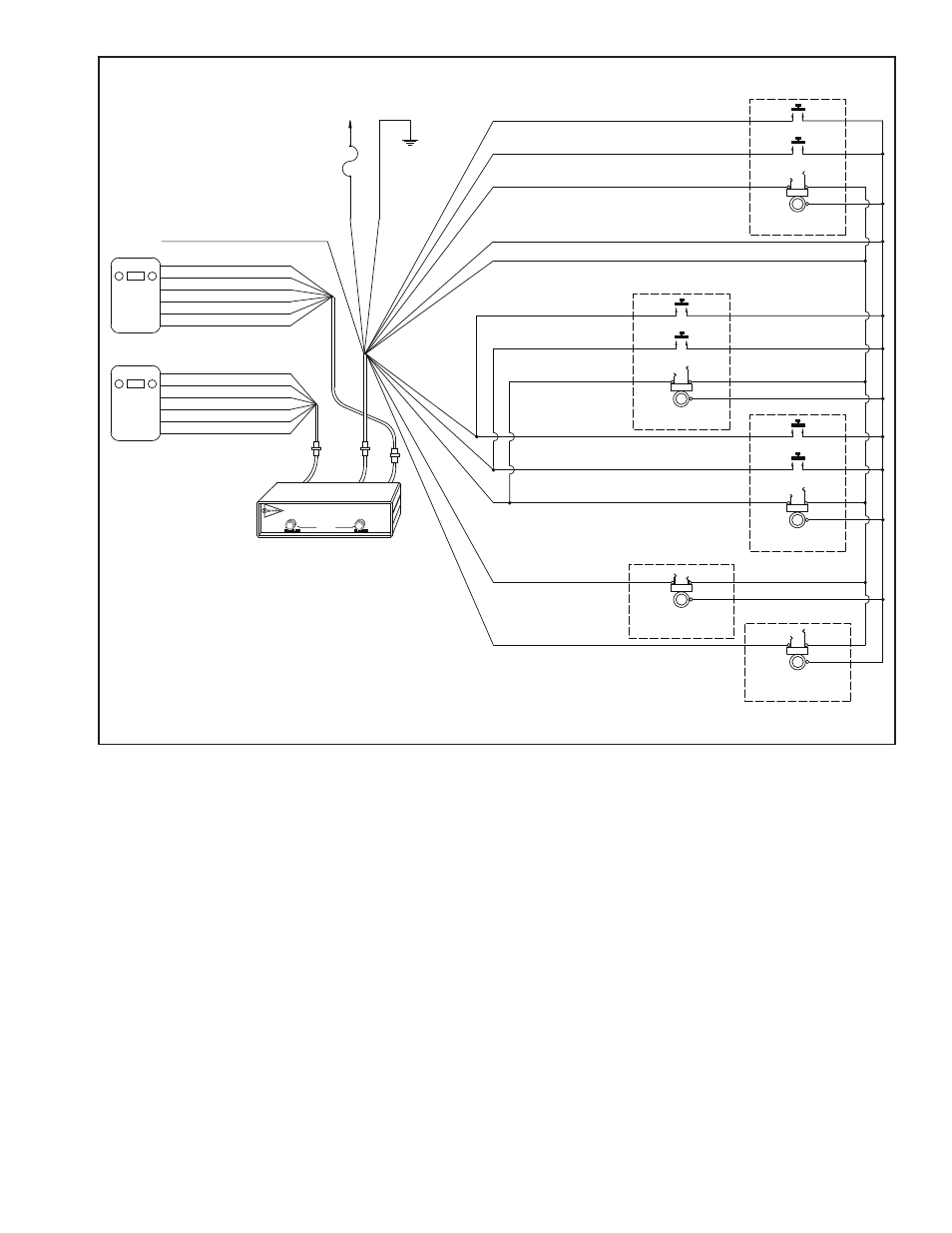
UltraSound CFR WIRING DIAGRAM
FIGURE 4
NOTES:
1) CONNECT EITHER VIOLET WIRE TO THE RADIO SPEAKER HI OUTPUT. CONNECT
THE REMAINING VIOLET WIRE TO SPEAKER LO.
2) CONNECT EITHER WHITE WIRE TO THE RADIO PUSH-TO-TALK (PTT) KEY LINE INPUT.
CONNECT THE REMAINING WHITE WIRE TO THE PTT KEY LINE RETURN (PTT LO).
(7) RED
+11 to +16
(1 AMP)
VOLTS DC
FUSE
CHASSIS
(12) GREEN
GROUND
MIC HI
PTT LO
MIC LO
PTT HI
SPEAKER HI
SPEAKER LO
(6) WHITE
(4) BLACK
(1) BROWN
(3) VIOLET
(5) WHITE
(2) VIOLET
NOTE 2
NOTE 2
NOTE 1
NOTE 1
SPEAKER LO
SPEAKER HI
PTT HI
MIC LO
PTT LO
MIC HI
(2) VIOLET
(1) BROWN
(4) BLACK
(5) WHITE
(3) VIOLET
(6) WHITE
NOTE 1
NOTE 1
NOTE 2
NOTE 2
RADIO 2
123
123
RADIO 1
P1
J1
J2
P2
J3
P3
INTERCOM UNIT
UltraSound
INTERCOM
UltraSound CFR
(15) WHITE / YELLOW NOT USED
(2) WHITE / RED
(1) WHITE / BLACK
(9) TAN
(3) BLUE
(8) TAN
(4) BLACK
HEADSET JACK
OFFICER
RADIO 1 PTT SWITCH
(5) ORANGE
RADIO 2 PTT SWITCH
TIP
BARREL
RING
HEADSET JACK
CREW #1
RING
TIP
BARREL
HEADSET JACK
CREW #2
TIP
RING
BARREL
(10) WHITE / BLUE
(11) WHITE / ORANGE
(6) WHITE / GREEN
(10) WHITE / BLUE
(11) WHITE / ORANGE
(6) WHITE / GREEN
HEADSET JACK
PUMP PANEL
PUMP PANEL OPTION
RADIO 1 PTT SWITCH
RADIO 2 PTT SWITCH
TIP
BARREL
RING
HEADSET JACK
DRIVER
RADIO 1 PTT SWITCH
RADIO 2 PTT SWITCH
TIP
BARREL
RING
Flexible four conductor hook-up wire is provided with each
system to connect each headset jack and PTT switch to the
UltraSound unit’s Headset Jack and PTT Switch Cable. Enough
wire is provided for a typical vehicle installation. If required,
additional hook-up wire can be purchased through your
Sigtronics dealer.
Each headset jack requires three wires. Each PTT switch
requires two. If an Officer’s PTT switch and headset jack are
mounted near each other, only four wires are needed.
Refer to the UltraSound Wiring Diagram (for CFR see Figure
4 above, for Dual-CFR see Figure 5 on page 6) for the exact
wiring information.
The connections between the Headset Jack and PTT Switch
Cable and the hook-up wire should be soldered and insulated
for reliability. Do not use crimp type splices. They can become
intermittent over time. Use a good quality electrical tape, or
better yet, use heat shrink tubing to cover the soldered
connections. The connections to the headset jacks and PTT
switches will also have to be soldered. See Figure 3 on page
4 for jack terminal identification.
We also do not recommend using screw type terminal strips
for intercom connections. There have been several instances
where terminal strips introduced high levels of electrical
noise like alternator whine into the intercom system. It is
acceptable however to tie the intercom red and green power
wires to existing vehicle terminal strips.
The best place to run the wiring between the unit and the
jack and PTT switches is out of sight. It should be run behind
vehicle panels and/or up in the headliner. This will reduce the
chance of personnel or equipment catching on or damag-
ing the wiring. Wire routing should take into account normal
vehicle operations. Wires should not interfere with any of the
vehicle’s controls, compartments, or doors. If the vehicle’s cab
tilts up for engine servicing, run wiring along the existing
vehicle wiring bundle. Make sure that wiring does not inter-
fere or restrict the tilting operation. Also, make sure that the
tilting operation will not cut or sever the wiring.
Make sure that the wiring does not rest on sharp edges. Over
time the vehicle’s vibration may cause a sharp edge to cut
into the wire. Use the provided wire grommets wherever
the four conductor wire goes through the hole into a jack
5