Stl-300 stoplite, Tactical light & laser, Contact – SIG SAUER STL-300J Stoplite User Manual
Page 2: Instructions, Statement of liability, Warranty statement, Install battery, Position batteries as shown in picture, Light must be on to select or change modes, Last selected mode is retained until changed
cONTAcT
18 Industrial Drive, Exeter, NH 03833 • (603) 772-2302 ext. 3 • www.sigtac.com
P/N 8500190 Rev 1
STL-300 STOPLITE
®
TacTIcaL LIghT & LaSEr
INSTRUcTIONS
Install battery:
n
Open door at bottom of grip using coin or screwdriver
n
Position batteries as shown in picture
n
Close battery door and secure using coin or screwdriver
Getting Started:
n
Turn on light by pressing light power button on side. Select steady or
strobe modes using 2 smaller side buttons.
n
Light must be ON to select or change modes.
n
Last selected mode is retained until changed.
n
Steady light mode
n
Strobe light mode
n
For Momentary Operation – depress and hold the large button on
back. For steady operation, press and release side power button.
n
Laser light mode
n
Laser functions independently of either light mode.
Press red button on back of laser aiming module to turn on/off.
For Remote Operation (optional):
n
Install remote momentary on/off pressure switch into remote
switch port.
n
Squeeze remote switch pad at end of cord and hold for momentary
operation. Last selected mode (steady or strobe) is retained
until changed.
Note: This product features digital power management. When battery power drops below
a preset level, the unit shuts down to protect the internal circuitry and prevent a battery
overheating condition. If this occurs, the battery needs replacement.
Mounting on Firearm:
n
Depress quick release bar and hold
n
Slide STL-300 STOPLITE onto rifle accessory rail
n
Release quick release bar and move STL-300 STOPLITE into place.
n
Secure STL-300 STOPLITE firmly on rail by hand tightening locking
both retention screws.
Laser Aiming Module Adjustment
n
Use screwdriver or coin to make necessary adjustments.
n
Rotate TOP adjustment screw clockwise to move laser UP.
n
Rotate SIDE adjustment screw clockwise to move laser LEFT.
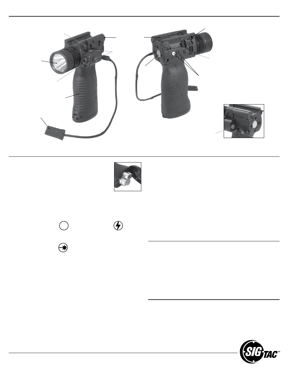
Independent laser
On/Off button
Quick release
bar and rail
attachment
Ergonomic
grip contour
Accessory rail
mounting point
Locking retention
screw
450 Lumen*
cREE LED
Light and
laser modes
Laser
aiming
module
Laser aiming
adjustments
Steady on/off
button
Luminous
momentary
mode light
button
Remote momentary
on/off pressure switch
STATEMENT OF LIABILITY
This device is classified as a FIREARMS ACCESSORY and is sold by us with the specific
understanding that we are not responsible in any manner whatsoever for its safe
handling or resale under local laws and regulations. SIGTAC shall not be responsible
in any manner whatsoever for malfunctioning of the firearm, for physical injury or for
property damage resulting in whole or in part from (1) criminal or negligent discharge, (2)
improper or careless handling, (3) unauthorized modifications, (4) defective, improper,
hand-loaded, or reloaded ammunition, (5) corrosion, (6) neglect, or (7) other influences
beyond our direct and immediate control. This limitation applies regardless of whether
liability is asserted on the basis of contract, negligence or strict liability (including
any failure to warn). Under no circumstances shall SIGTac be liable for incidental or
consequential damages, such as loss of use of property, commercial loss and loss of
earnings or profits.
WARRANTY STATEMENT
SIGTac warrants that our sight and illumination tool products are free from defect in parts and
workmanship for a period of ninety (90) days from original date of purchase. At our discretion,
we will repair, replace, or refund your original purchase price of this product if it is determined
to be defective. Normal wear and tear, including lamps burning out, batteries draining, and
switches wearing out, is not covered, nor is damage resulting from abuse, neglect, battery
leakage, or altering this product from its original state.