Control panel overview – Shellab SCO12WE-2 User Manual
Page 9
8
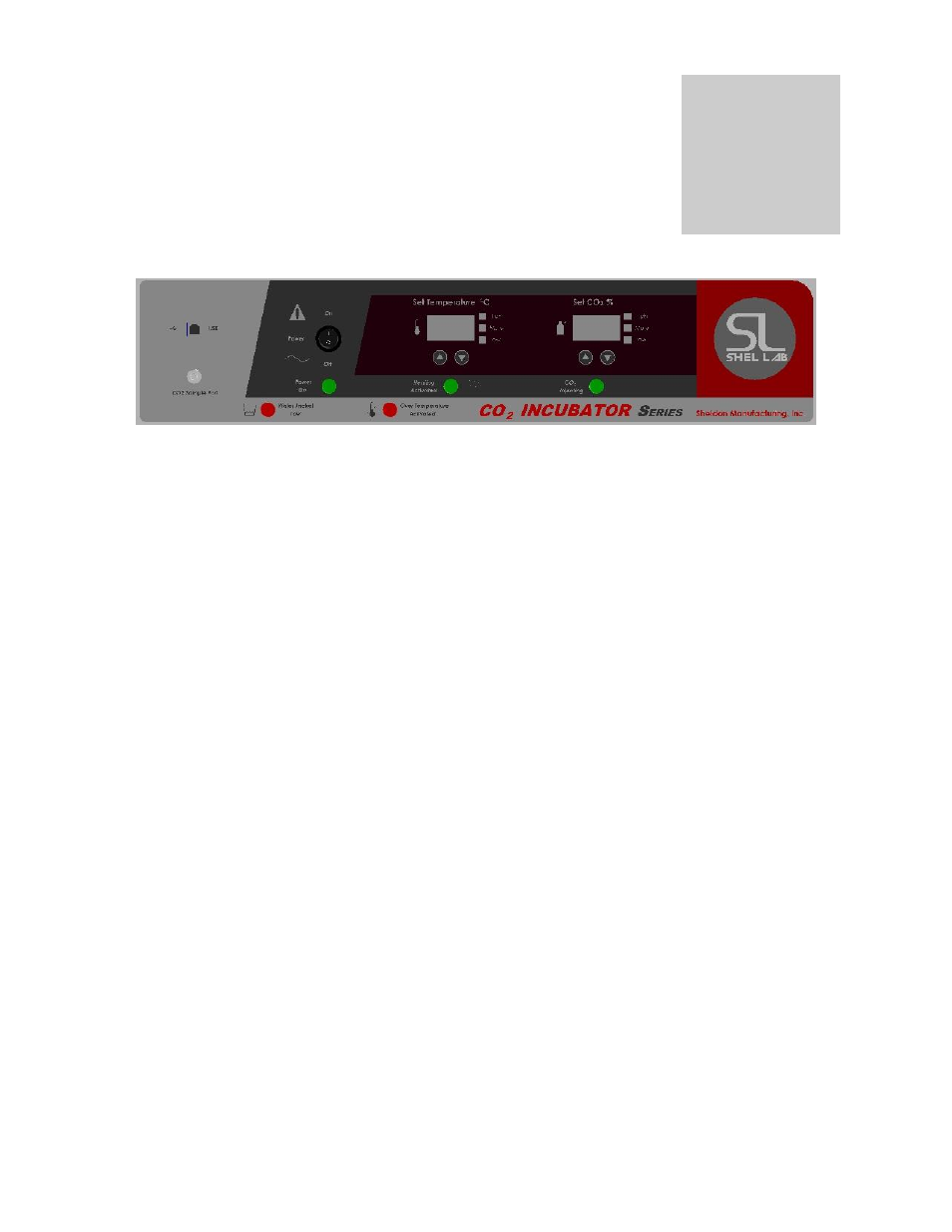
CONTROL PANEL OVERVIEW
Units with a detachable cord have a fused inlet located at the top rear of the control panel. This inlet has a
recessed male plug, fuse, and an EMI filtering system designed to filter out electrical interference. This inlet
also prevents any internally generated interference from feeding out to the power grid. All controls are
located on the front panel, except the Over Temperature Safety which is located at the back and the Door
Temperature Controller which is located on the liner of the outer door.
4.1
Power Switch: The I/O (ON/OFF) switch controls all of the power for the incubator and must be in
the I/ON position before any systems are operational. Both Temperature and CO
displays will
illuminate when the power switch is in the ON position.
4.2
Water Low Light: This pilot lamp is on whenever the internal water jacket float switch has been
tripped to the closed position. When the water drops low enough the float switch closes the circuit
turning on the indicator light.
4.3
Safety Activated light: This pilot lamp is on whenever the Over Temperature Safety thermostat
has been activated and taken control of the element. During normal operating conditions this
indicator light should never be on.
4.4
Temperature Control: This controller is marked C
and indicates the actual temperature within the
chamber to .1
C. The UP/DOWN buttons are used for imputing the set point, calibrating the display,
and muting or unmuting the audible alarm. The HIGH and LOW alarm indicators will light whenever
there is an alarm condition associated with the temperature within the chamber. The MUTE indicator
will light whenever the audible alarm has been deactivated.
4.5
Heating Light: This pilot lamp is on whenever the Temperature Controller has activated the heating
elements to reach and maintain set point.
4.6
CO2 Control on Water Jacket Incubators:
The controller is marked “CO2 %” and has a
resolution of .1 %. It has an up and down arrow that is used for imputing CO2 set points,
calibrating the CO2 concentration level, and muting or unmuting the audible alarm. It also has
three led indicating lights for alarm conditions, one for high CO2 levels, one for low CO2 levels,
and one for alarm mute. On some older model the up and down arrows can also be used to reset
the control integrator value. On newer Models it isn’t necessary, but can be done also.
4.7
Injection Light: This pilot lamp is on whenever the CO
controller is injecting the CO
into the
chamber.
4.8
Over Temperature Safety Control (OTP): Located at the back of the control panel adjacent to the
power inlet. This is a hydraulic thermostat that is wired between the Main Temperature Control and
the heating element and functions as an override control. If at any time the Temperature Control
fails in the ON position and the temperature in the chamber rises above its set point, the OTP is
activated and maintains temperature at its own set point. Note that the HEATING indicator will
continue to function under the control of the OTP. It is not recommended that the unit be allowed to
operate for an extended period of time using only OTP as temperature uniformity will suffer.
4.9
CO
Sample Port: This is located on the lower right side panel. A sample can be drawn to
Section
4