Figure 3 – Shellab SCO12WE-2 User Manual
Page 13
12
D.
After the Main Temperatures are set and adjusted, the Overtemperature Safety Control
needs to be set. Do this by turning the OTP Control Knob counterclockwise until the
Overtemperature Light comes on (this will blink in sequence with Heating Activated Light).
Next, slowly turn the knob clockwise until the light goes off, then turn the knob another 8
degrees approximately. This should set the Overtemperature 1 degree above the Main
Temperature set point.
5.9
CO
Supply System and Control System: The CO
system is rated for pressures between 15
and 20 PSI, which should never be exceeded at any time. Prior to any attempt to hook up or run
the CO2 Control System, the water jacket must be filled and the temperatures adjusted as
noted in Section 5.7 and 5.8.
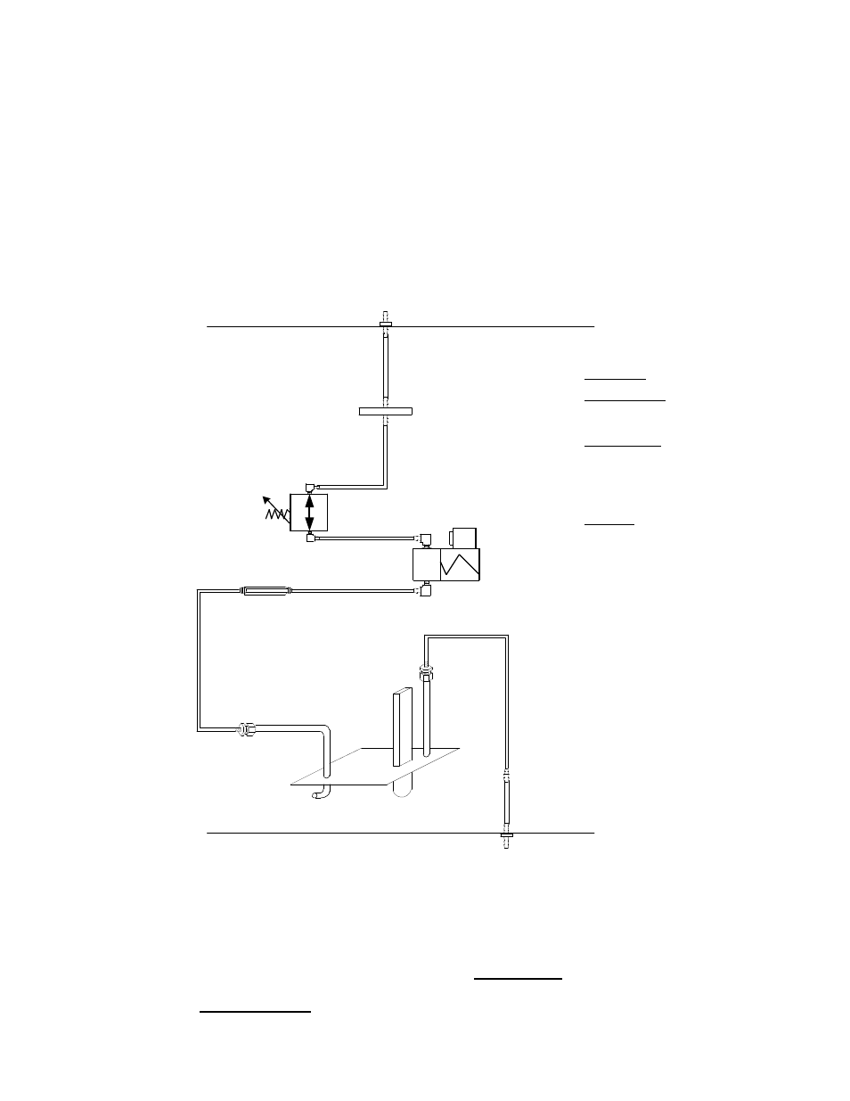
Figure 3
CO2 GAS INLET
IN BACK
SAMPLE PORT
IN FRONT
HOSE ADAPTER
¼” To 5/16"
SL# 6950502
BARBED THRU-WALL
SL# 3100734
5/16" TUBING
CLEAR PLASTIC
SL# 8500512
6"
GAS FILTER
SL# 2800525
5/16" TUBING
CLEAR PLASTIC
SL# 8500512
2.5"
SENSOR BRACKET ASSY.
SL# 950-00011
I.R. Sensor
SL# 832510
¼” HOSE ADAPTER
BARBED/THREADS
SL# 31100519
¼”HOSE ADAPTER
BARBED/THREADS
SL# 31100519
PRESSURE
REGULATOR
SL# 7150510
SOLENIOD
SL# 8600528
¼” ELBOW ADAPTER
BARBED/THREADS
SL# 3100517
1/4" TUBUNG
BLACK PLASTIC
SL# 8500516
10"
1/4" TUBING
BLACK PLASTIC
SL# 8500516
8"
1/4" TUBING
BLACK PLASTIC
SL# 8500516
5"
1/4" TUBING
BLACK PLASTIC
SL# 8500516
7"
1/4" TUBING
COPPER
SL# 8530500
2.5"
1/4" TUBING
COPPER
SL# 8530500
36"
¼” RESTRICTER ASSY.
SL# 7100504 & 3100517
1/4" TUBING
BLACK PLASTIC
SL# 8500516
32"
TUBING LIST
5/16" CLEAR PLASTIC
6" INLET - FILTER
2.5" ADAPTER – SAMPLE PORT
1/4" BLACK PLASTIC
10" FILTER - REGULATOR
8" REGULATOR – SOLENOID
5" SOLENOID – RESTRICTER
7" RESTRICTER – ADAPTER
32" ADAPTER – ADAPTER
1/4" COPPER
30" ADAPTER – CHAMBER
2.5" CHAMBER - ADAPTER
9851229
A.
The CO
inlet fitting is located on the back of the incubator near the top (see figure 3). It is
marked "CO
TO CHAMBER". The supply hose with in-line CO
filter (supplied with your
accessories) connects from this fitting to the CO
tank and regulator. The initial supply
pressure should be 20 PSI.
B.
It is highly recommended that a good quality DUAL STAGE pressure regulator be used on
the CO
tank. The dual stage regulator will have two pressure gauges with a 0-60PSI
LOW-PRESSURE range. The high pressure gauge will indicate the pressure within the
tank. The low pressure gauge will indicate the pressure on the supply hose to the incubator.