SeaLand VacuFlush 4848 Toilet User Manual
Vacuflush, 4848 toilet installation guide
STEP 12: Several flush switch options can be ordered from Dometic. Instructions for installing the
basic Dometic flush switch are on the next page.
Two other available types fit either VIMAR or GEWISS panels and housings. The VIMAR and
GEWISS panels use one switch for both “Flush” and “Add Water” functions. Instructions are
included with each flush switch assembly.
Install flush switch in desired location and route electrical cables/wiring through the 1 3/4-inch
(44 mm) hole to the toilet. Leave enough cable to connect to the toilet (fig. 11). (The cable supplied
with the basic Dometic flush switch will have a Deutsch connector.)
STEP 13: WITH POWER OFF, route electrical cables/wiring from vacuum generator and power
source through 1 3/4-inch (44 mm) hole (fig. 11). Leave enough wire above the floor or through the
wall to connect to toilet. (See wiring diagrams on next page. If Deutsch connectors (shown) are
not being used, refer to wiring diagram to make proper connections in Step 15).
STEP 14: Secure the toilet mounting brackets to the floor using the #14 x 2 ½-inch (65 mm) hex
washer head screws and support plates provided. Be sure to mount the brackets as shown on the
template (fig. 12).
STEP 15: Set the toilet in front of the discharge adapter. Connect the flexible water hose to the
1/2-inch female NPT fitting on the inlet water line. Connect the cable/wiring from flush switch
to the toilet’s flush switch-status panel cable/wiring. Connect the cable/wiring from vacuum
generator and power source to the toilet’s vacuum generator-power source cables/wiring (fig. 13).
IMPORTANT – DO NOT ATTEMPT TO SLIDE THE TOILET OVER THE DISCHARGE ADAPTER.
THE TOILET MUST BE SET DOWN INTO THE ADAPTER TO PREVENT POSSIBLE DAMAGE.
STEP 16: Lubricate the O-ring around the bottom of the toilet base with liquid soap or silicone
spray or grease. Pick up the toilet and insert plastic base assembly into discharge adapter. Make
sure mounting brackets on floor do not interfere with bottom of ceramic toilet (fig. 14). If the
mounting brackets interfere, loosen mounting screws and adjust bracket location accordingly.
STEP 17: Insert the two plastic flange bushings into the toilet mounting holes and secure the
toilet to the mounting brackets with the two flat head wood screws provided (fig. 15). Be sure to
drive fasteners into mounting brackets at a downward angle.
STEP 18: Press the decorative fastener covers over the flange bushings (fig. 16).
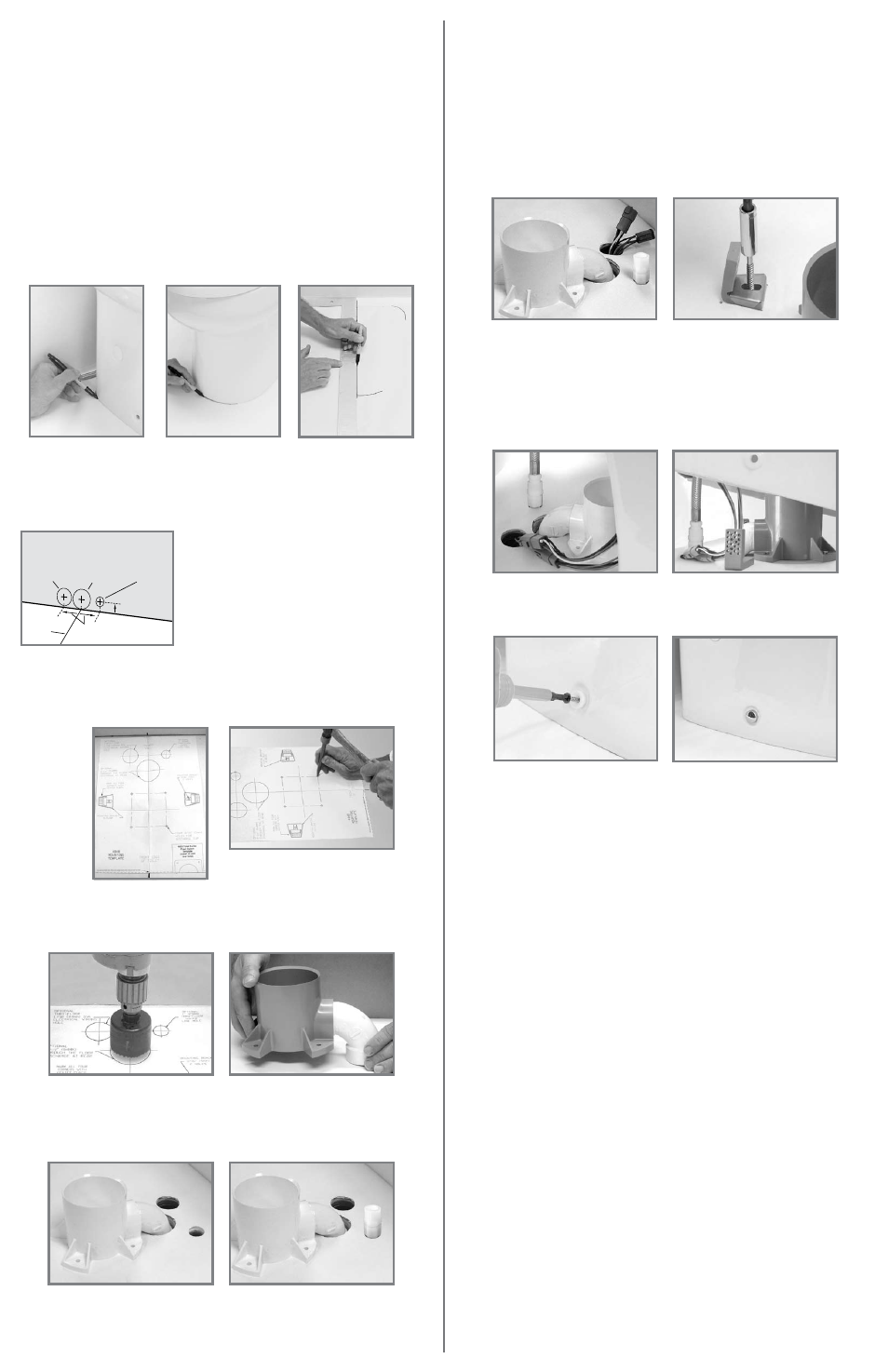
STEP 1: Carefully unpack toilet and place it in the position intended. Center the toilet in the
selected position and assure that adequate clearance is available for opening the seat and lid.
Check the front and sides of the toilet to insure that it will set flat against the floor. Determine the
best location for the flush switch panel. It is recommended that it be close to the toilet but not
hidden by the toilet lid in the “up” position. Avoid a location susceptible to direct water spray.
STEP 2: Mark the floor at the rear corners and the front center of the ceramic bowl. Remove the
ceramic bowl and set aside (figs. 1, 2).
STEP 3: Measure the distance between the rear corner marks on the floor and divide by 2 to find
the centerline. Using a carpenter’s square, draw a centerline on the floor that intersects the mark
for the front center of the bowl (fig. 3).
STEP 4: Choose an inlet configuration for the electrical wiring and water line hole location: (a)
through the rear wall, or (b) through the floor behind the discharge adapter.
STEP 5: For discharge through the rear wall, measure up 1 inch (25 mm) from the toilet
centerline. For the electrical cables, measure up 1 inch (25 mm) and 2 inches (51 mm) to the left of
the centerline. For the water line, measure up 1 inch (25 mm) and 2 inches (51 mm) to the right of
the centerline (fig. 4). Mark the hole locations.
Toilet Requirements:
• 2 GPM (7.6 lpm) or larger water pump.
• 1/2-inch (12.7 mm) water line terminating in a 1/2-inch female NPT fitting (to connect to toilet
water supply hose).
• 12 VDC or 24 VDC through a fuse or circuit breaker of sufficient size to protect wiring. Circuit
board fuse resets by turning power off and on. Refer to installation codes for proper wire sizes.
VacuFlush
®
4848 ToileT iNsTallaTioN GuiDe
Fig. 1
Fig. 2
Fig. 3
These locations are for the discharge,
water and electrical supply line holes in
through-the-wall installations.
STEP 6: Align the 4848 toilet mounting template along the centerline mark with the front edge of
the template flush with the mark for the front edge of the toilet bowl (fig. 5). Tape the template to
the floor.
STEP 7: Using a center punch, mark all six 3/16-inch (5 mm) diameter hole locations (fig. 6) and all
through-the-floor discharge and water/electrical supply holes, as determined in Step 4. Also mark
the locations of the corners of the toilet mounting brackets.
Fig. 5
Fig. 6
STEP 8: Drill the discharge hole – 2.5-inch (64 mm) dia. through the floor (fig. 7) or 2-in. (51 mm)
through the wall. Where required, drill the 1-inch (25mm) dia. water line hole and 1.75-inch
(44 mm) dia. electrical cable hole. Remove the template from the floor.
STEP 9: Using PVC primer and solvent cement, solvent weld the desired outlet fittings to the
discharge adapter (fig 8). Allow to cure before handling.
STEP 10: Mount discharge adapter to the floor (fig. 9) with #14x1 in. pan head phillips head
screws and flat washers provided. Complete the plumbing to vacuum tank or vacuum generator.
Use 1½-inch OdorSafe Plus flexible sanitation hose or 1½-inch PVC schedule 40 pipe.
STEP 11: Route 1/2-inch (13 mm) diameter water line from the fresh water source through the
1-inch (25 mm) hole in the wall or floor and attach a 1/2-inch female NPT fitting (fig. 10).
Note: A
shut-off valve should be placed in the water line to the toilet for maintenance or repair.
Fig. 14
Fig. 13
Fig. 16
Fig. 15
SEE NEXT PAGE FOR DOMETIC WALL-MOUNTED FLUSH SWITCH
INSTALLATION AND TOILET SYSTEM WIRING DIAGRAM.
Fig. 7
Fig. 9
Fig. 10
Fig. 8
Fig. 11
Fig. 12
wall
FlooR
toilet
centerline
1 in.
(25mm)
2 in.
(51 mm)
Fig. 4
electric cable
location
1.75-in. dia.
(44mm)
discharge hose
location
2-in. dia.
(51mm)
water line location
1-in. dia.
(25mm)