SeaLand VacuFlush 4809 Toilet User Manual
Vacuflush, 4809 toilet installation guide
STEP 1: Carefully unpack toilet and place it in the position intended. Center the toilet in the
selected position and assure that adequate clearance is available for opening the seat and lid.
Check the front and sides of the toilet to insure that it will set flat against the floor. Determine the
best location for the flush switch panel. It is recommended that it be near the toilet but not hidden
by the toilet lid in the “up” position. Avoid a location susceptible to direct water spray.
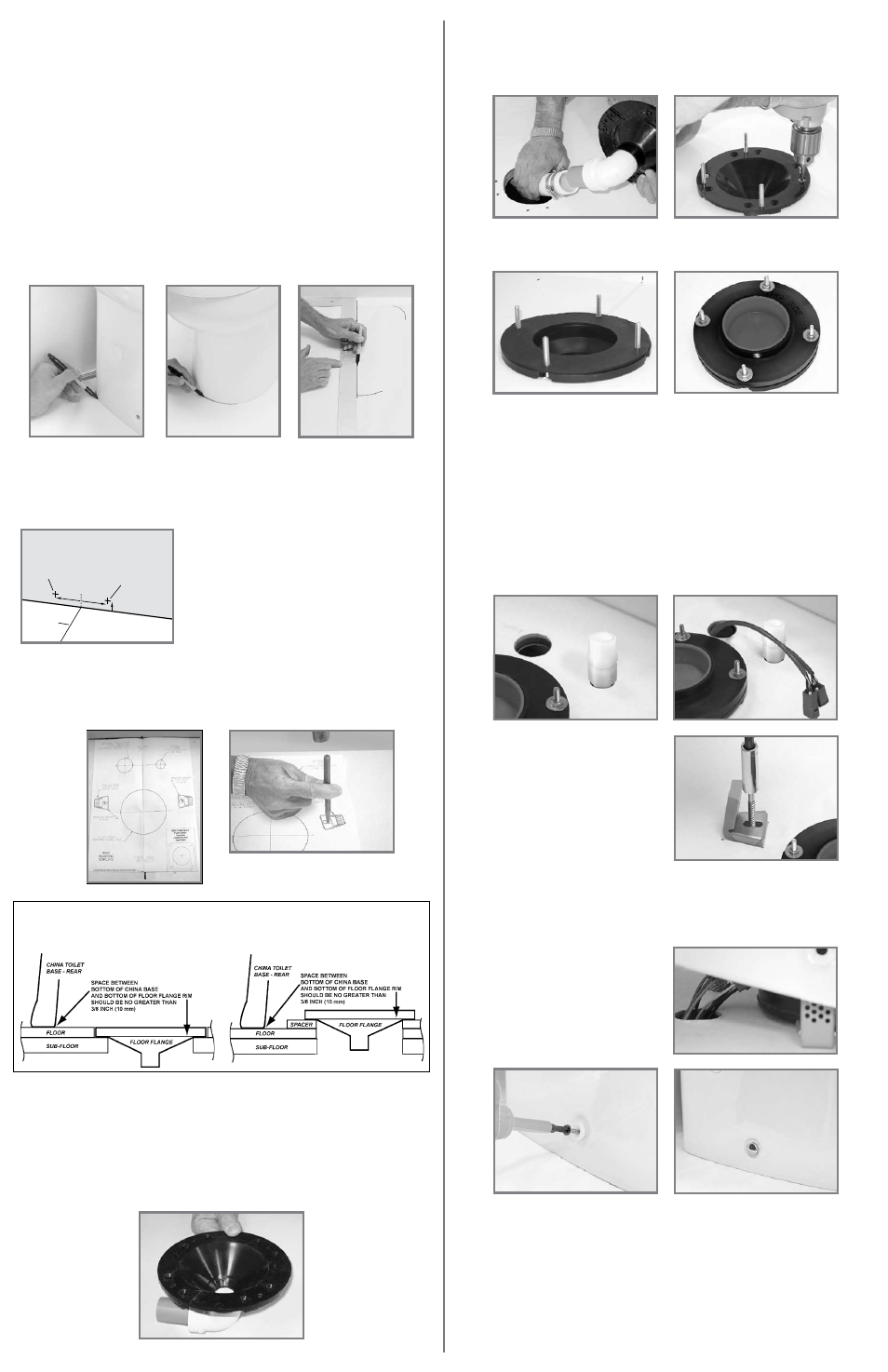
STEP 2: Mark the floor at the rear corners and the front center of the ceramic bowl. Remove the
ceramic bowl and set aside (figs. 1, 2).
STEP 3: Measure the distance between the rear corner marks on the floor and divide by 2 to find
the centerline. Using a carpenter’s square, draw a centerline on the floor that intersects the mark
for the front center of the bowl (fig. 3).
STEP 4: Choose an inlet configuration for the electrical wiring and water line hole location: (a)
through the rear wall, or (b) through the floor.
STEP 5: For electrical cables/wiring and water line installations
through the rear wall, measure
up a minimum of 1 inch (25 mm) and 2 inches (51mm) to the right of the centerline (fig. 4) for the
electrical cables, and 2 inches (51 mm) to the right of the centerline for the water line. Mark the
hole locations.
Toilet Requirements:
• 2 GPM (7.6 lpm) or larger water pump.
• 1/2-inch (12.7 mm) water line terminating in a 1/2-inch female NPT fitting (to connect to toilet
water supply hose).
• 12 VDC or 24 VDC through a fuse or circuit breaker of sufficient size to protect wiring. Circuit
board fuse resets by turning power off and on. Refer to installation codes for proper wire sizes.
VacuFlush
®
4809 ToileT iNsTallaTioN GuiDe
Fig. 1
Fig. 2
Fig. 3
These locations are for the water and electrical
supply line holes in through-the-wall installations.
wall
FlooR
toilet
centerline
water line
location
1 in.
(25 mm)
2 in.
(51 mm)
Fig. 4
STEP 6: Align the 4809 toilet mounting template along the centerline mark with the front edge of
the template flush with the mark for the front edge of the toilet bowl (fig. 5). Tape the template to
the floor.
STEP 7: Using a center punch, mark the center locations for the discharge flange hole, mounting
bracket holes (fig. 6), the four corners of each mounting bracket, and the center of the water line
and electrical wiring holes (if routing these through the floor). Remove the template from the floor.
Fig. 5
Fig. 6
Below-Floor installation
above-Floor installation
iMPoRTaNT: The preferred floor flange installation method is to mount the flange directly on the
finished floor. However, if the bottom of floor flange and bottom of ceramic toilet must be mounted
at different heights, the floor flange must be mounted within 3/8-inch (10 mm) of the bottom of the
toilet (see illustrations below) or leakage will result.
STEP 8: Cut out the 4-3/4-inch (120 mm) diameter discharge flange hole. Drill the two 3/16-inch
(5 mm) holes mounting bracket fastener holes. Where required (floor or wall), drill the 1-inch
(25 mm) diameter water line hole and 1 3/4-inch (44 mm) electrical wiring hole.
STEP 9: VERTICAL DISCHARGE HOSE – Using PVC primer and solvent cement, attach the hose
adapter directly into the discharge flange outlet. Allow to cure before handling. HORIZONTAL
DISCHARGE HOSE – Using PVC primer and solvent cement, attach the elbow directly to the
discharge flange outlet. Then attach the hose adapter into the elbow (fig. 7). Allow to cure before
handling.
STEP 10: Insert the discharge flange into the hole with the elbow pointing in the direction of the
discharge plumbing. Mark the floor through the eight countersunk mounting holes. Remove the
flange and drill the eight pilot holes with an 11/64-inch (4 mm) drill bit.
Fig. 7
STEP 11: Route the vacuum hose from the vacuum generator or vacuum tank up through the
discharge flange hole. Lubricate the inside of the hose with liquid dishwashing soap and install the
hose onto the adapter. Secure the connection with two stainless steel hose clamps (fig. 8).
STEP 12: Insert four T-bolts into the discharge flange from the underside.
STEP 13: Insert the discharge flange and connected hose or pipe into the discharge hole and
secure to the floor with the eight #12x1-1/2-inch flat head screws provided (fig. 9).
STEP 14: Install the flange gasket over the T-bolts (fig. 10).
STEP 15: Install floor flange adapter with words “THIS SIDE UP” facing up. Tighten adapter to
floor flange using four flat washers and hex nuts. Tighten in criss-cross pattern (fig. 11).
STEP 16: Route 1/2-inch (13 mm) diameter water line from the fresh water source through the
1-inch (25 mm) hole in the wall or floor and attach a 1/2-inch female NPT fitting (fig. 12).
Note: A shut-off valve should be placed in the water line to the toilet for maintenance or repair.
STEP 17: Several flush switch options can be ordered from Dometic. Instructions for installing the
basic Dometic flush switch are on the next page.
Two other available types fit either VIMAR or GEWISS panels and housings. The VIMAR and
GEWISS panels use one switch for both “Flush” and “Add Water” functions. Instructions are
included with each flush switch assembly.
Install flush switch in desired location and route electrical cables/wiring through the 1 3/4-inch
(44 mm) hole to the toilet. Leave 12 inches (305 mm) of cable to connect to the toilet (fig. 13).
(The cable supplied with the basic Dometic flush switch will have a Deutsch connector.)
Fig. 8
Fig. 9
Fig. 10
Fig. 11
Fig. 12
Fig. 13
Fig. 14
Fig. 15
Fig. 17
Fig. 16
SEE NEXT PAGE FOR DOMETIC WALL-MOUNTED FLUSH SWITCH INSTALLATION
AND TOILET SYSTEM WIRING DIAGRAM.
STEP 18: WITH POWER OFF, route electrical cables/wiring from vacuum generator and power
source through 1 3/4-inch (44 mm) hole (fig. 13). Leave at least 12 inches (305 mm) of wire above
the floor or through the wall to connect to toilet. (See wiring diagrams on next page. If Deutsch
connectors (shown) are not being used, refer to wiring diagram to make proper connections in
Step 20).
STEP 19: Secure the toilet mounting brackets to
the floor using the #14 x 2 ½-inch (65 mm) hex
washer head screws and support plates
provided. Be sure to mount the brackets as
shown on the template (fig. 14).
STEP 20: Set the toilet in front of the discharge
adapter. Connect the flexible water hose to the
1/2-inch female NPT fitting on the inlet water
line. Connect the cable/wiring from flush switch
to the toilet’s flush switch-status panel cable/
wiring. Connect the cable/wiring from vacuum
generator and power source to the toilet’s
vacuum generator-power source cables/wiring.
IMPORTANT – DO NOT ATTEMPT TO SLIDE THE TOILET OVER THE DISCHARGE ADAPTER.
THE TOILET MUST BE SET DOWN INTO THE ADAPTER TO PREVENT POSSIBLE DAMAGE.
STEP 21: Lubricate the O-ring around the bottom of the toilet base with liquid soap or silicone
spray or grease. Pick up the toilet and insert plastic base assembly into discharge adapter. Make
sure mounting brackets on floor do not interfere with bottom of ceramic toilet (fig. 15). If the
mounting brackets interfere, loosen mounting screws and adjust bracket location accordingly.
STEP 22: Insert the two plastic flange bushings
into the toilet mounting holes and secure the
toilet to the mounting brackets with the two flat
head wood screws provided (fig. 16). Be sure
to drive fasteners into mounting brackets at a
downward angle.
STEP 23: Press the decorative screw covers
over the flange bushings (fig. 17).
2 in.
(51 mm)
electric cable
location