0 communication protocol, 1 uart settings, 2 packet format – ScanTool STN Bootloader User Manual
Page 4: 3 control characters, 4 crc, Communication protocol, Uart settings, Packet format, Control characters, Stn bootloader
STN Bootloader
4.0 Communication
Protocol
STN bootloader employs a basic communication
protocol that is robust, simple to use, and easy to
implement.
Flow control is built into the protocol. Thus, for
every received command, there is a response (an ACK
or a NACK).
All multibyte values are big-endian and are
transmitted most significant byte first.
4.1 UART Settings
The bootloader communicates with the host via
UART. The following communication settings are used:
• 8 data bits
• No
parity
• 1 stop bit
• Automatic baud rate detection
The bootloader supports a wide range of baud
rates. All standard RS-232 baud rates are supported in
addition to a few higher baud rates. The following
formula can be used to calculate all supported baud
rates (expressed in bits per second):
Baud Rate
divisor
10,000,000
=
,
where divisor is an integer between 1 and 65,536.
Baud rate is automatically detected during the
reception of the first
command packet. The bootloader will reply on the
same baud rate.
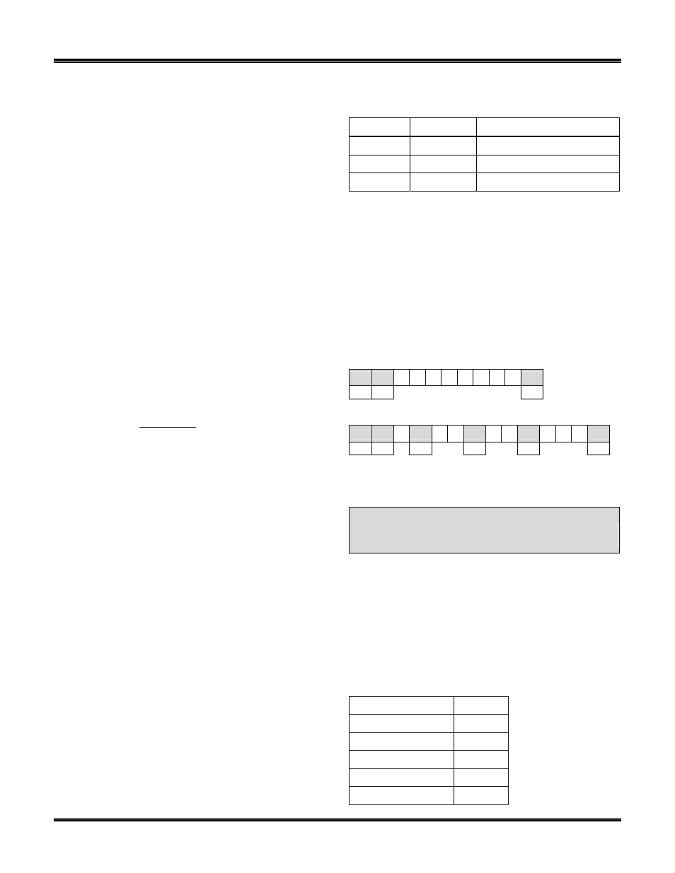
4.2 Packet Format
All data that is transmitted to or from the device
follows this basic packet format:
where each <…> represents a byte and […] represents
the data field. The start of a packet is indicated by two
‘Start of TeXt’ control characters (
terminated by a single ‘End of TeXt’ control character
(
16-bit CCITT CRC.
4.3 Control Characters
Three control characters have special meaning.
Two of them,
the previous section. The third control character is the
section. Table 1 provides a summary of the three
control characters.
Table 1 – Control Characters
Control Value Description
0x55
Start of TeXt
0x04
End of TeXt
0x05
Data Link Escape
The
interpreted in the data field or CRC as a control
character. Within the data field or CRC, the bootloader
will always accept the byte following a
and will always send a
0x04, and 0x05 that are part of data or CRC and
should not be interpreted by the receiver as control
characters.
For example, if a byte of value 0x55 is transmitted
as part of the data field, rather than as the
control character, the
before the 0x55 byte. In other words, the following
response packet (hex):
55 55 49
04
4C
55
8A
05
9B 92 04
STX STX
ETX
will be transmitted as
55 55 49 05
04
4C 05
55
8A 05
05
9B 92 04
STX STX DLE
DLE
DLE
ETX
The process of using
that may be misinterpreted as control characters, is
called “byte stuffing”.
Note:
Control characters are not considered data
and are not included in the CRC calcu-
lation.
4.4 CRC
The error detection during communication is
accomplished using a standard 16-bit CCITT CRC
(XModem) algorithm. Table 2 details the CRC para-
meters. Appendix B: CRC Sample Code lists sample
code for the CRC calculation.
Table 2 – CRC Parameters
Width
16 bits
Polynomial
0x1021
Initial Value
0x0000
Final XOR Value
0x0000
Reflection
none
Check Value
0x31C3
4 of 12
www.obdsol.com STNBLA