Pro i/o module operation guide – RED PRO I/O MODULE User Manual
Page 7
COPYRIGHT © 2012 RED.COM, INC
/
955-0010, Rev-B 7
PRO I/O MODULE
OPERATION GUIDE
RS232 PORT (AUX)
• 10 pin interface fixed programmable function GPIO pins
• Regulated 12V power at nominal 750 mA
• RS232 remote camera control
LEMO EAG.1B.310.CLN
Facing PRO I/O MODULE
LEMO EAG.0B.305.CLN
Facing PRO I/O MODULE
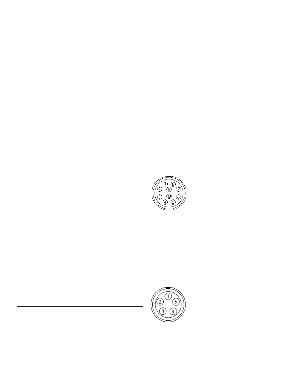
TIMECODE (TCODE)
• Pin 5 is time code output
• This connector supports SMPTE Timecode input
and output
• Pins 2 and 3 may be used together to receive a
balance SMPTE 12M serial timecode input, or pin 2
may be used by itself (leave pin 3 open) to receive a
single-ended SMPTE 12M serial time code input
PIN
DESCRIPTION
1
Camera Ground
2
Time code input - SMPTE single ended
3
Time code input - SMPTE double ended
4
48.00 KHz World Clock Output
5
Time code output
PIN
DESCRIPTION
1
Camera ground
2
Primary RS232 TX
3
(+) 12V
4
GPO B - Programmable tally output
Default: “record complete”
When active, present 3.3 V @0.04 amps
maximum between pins 1 and 4
5
SW 2 - Programmable function trigger
Default: “record: toggle”
To activate, momentarily short pin 5 to 1
6
GPI - Programmable trigger input
Default: “record start/stop”
To activate GPI trigger, mometarily short pin 6 to 1
7
SW 1 - Programmable function trigger
Default: “go to playback”
To activate, momentarily short pin 7 to 1
8
Primary RS232 RX
9
Secondary RS232 TX
10
Secondary RS232 RX