Safety, Mounting, Connections – RED PRO I/O MODULE User Manual
Page 4: Pro i/o module operation guide
4 955-0010, Rev-B
/
COPYRIGHT © 2012 RED.COM, INC
PRO I/O MODULE
OPERATION GUIDE
SAFETY
Important Safety Instructions
Read Before Using Your Pro I/O MODULE
• Heed all cautions and warnings in these instructions
• Follow these instructions when using the PRO I/O MODULE
• Keep these instructions with the PRO I/O MODULE
at all times
WARNING:
Do not modify, dismantle
or open this accessory as doing so
may expose you to electric shock
and serious injury.
To reduce the risk of fire or electric
shock, do not expose the PRO I/O
MODULE to rain or moisture. The unit is not water-
proof. Contact with water or other liquids could cause
permanent damage to the unit.
There are no user-serviceable parts inside. Alteration
or repairs made to this accessory, except by a RED au-
thorized service facility, will void the Limited Warranty.
CAUTION
: The Pro I/O Module is
NOT HOT SWAPPABLE – meaning
you cannot remove or install it while
the camera is powered on. Before
installing or removing the PRO I/O
MODULE, you MUST power down
CONNECTIONS
Default pin assignments are shown. Pins may be reassigned to different functions. See your camera’s Opera-
tion Guide for programming instructions. ‘
Mating cables are available form from RED.COM.
the camera. Failure to do so may result in damage to
the accessory and / or camera brain that will not be
covered under warranty.
Do not block any ventilation openings or obstruct
cooling fan airflow. Proper ventilation requires a mini-
mum 1/2” (1,25cm) clearance between the camera
ventilation openings and external surfaces. Verify
that objects that can block the fan intake and ex-
haust ports do not impede airflow. Failure to permit
adequate airflow may result in overheating of the Pro
I/O Module, degraded operation and in extreme situ-
ations, damage to the PRO I/O MODULE.
Clean only using a dry cloth. DO NOT use soaps,
detergents, ammonia, alkaline cleaners, and abrasive
cleaning compounds or solvents. These substances
may damage electronic circuitry.
Do not install near any heat sources such as radia-
tors, heat registers, stoves, or other apparatus that
produce heat.
Only use attachments/accessories specified by the RED.
Refer all service and repair to qualified RED service
personnel.
MOUNTING
Follow mounting instructions included in your cam-
era’s Operation Guide
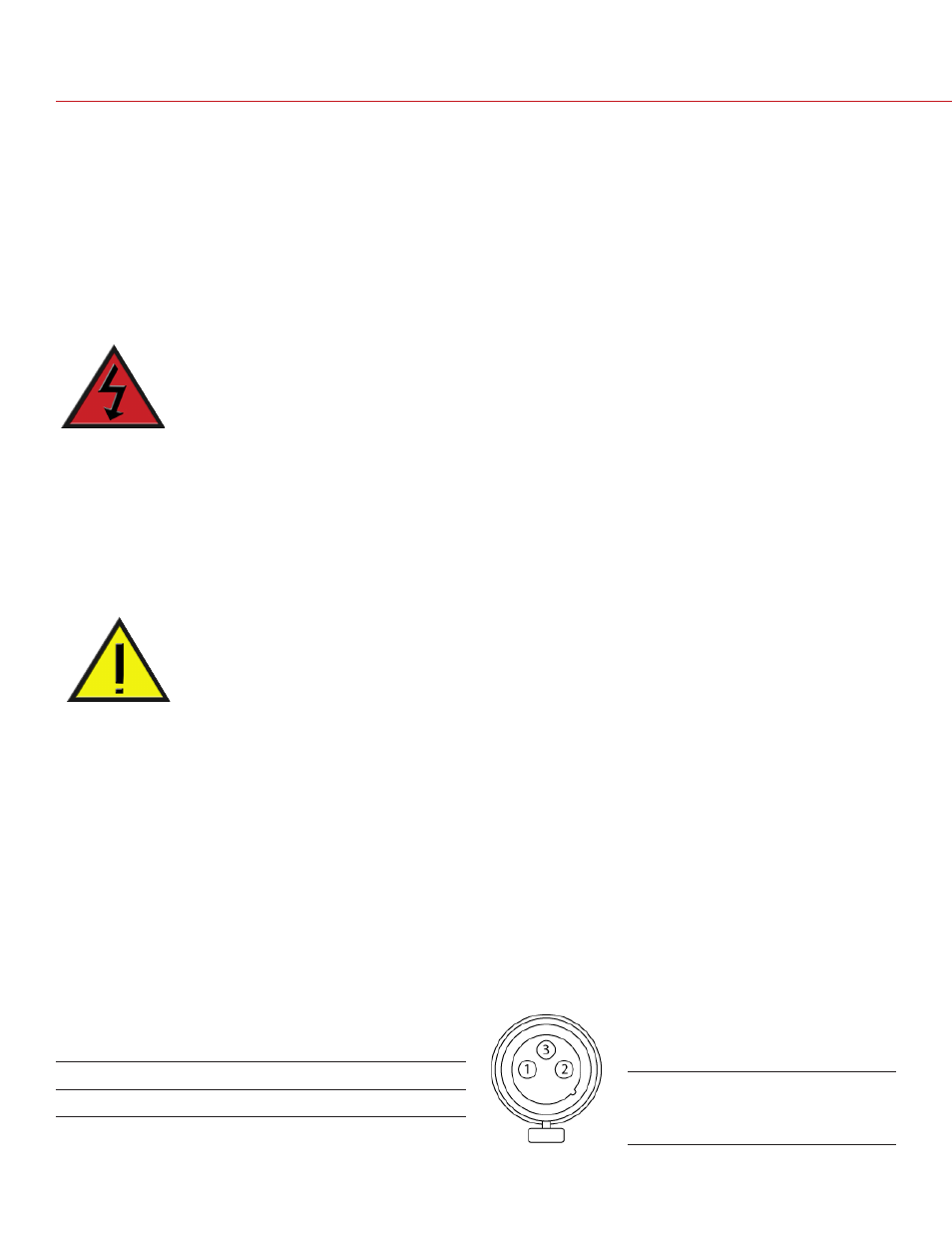
AUDIO INPUTS (3,4)
• Two three-pin XLR connectors provide input for
audio channels 3 & 4
• Each port supports 48V 10mA phantom power
• Each input may be independently set to either line
or microphone level
• If a channel is set to microphone, user can inde-
pendently enable its 48V phantom power output
3-PIN XLR
Facing PRO I/O MODULE
PIN
DESCRIPTION
1
Camera ground
2
Mic/Line input (+) 48V phantom power
3
Mic/Line input (-) 48V phantom power